Procure the Repeated Cable Pattern as a Defined Assembly
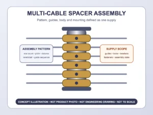
A multi-cable spacer assembly organizes several cable rows through one coordinated unit or set of matched parts. It is useful when the buyer wants the cable count, row centers, guides, body, end connections, and installation sequence controlled under one assembly description instead of buying unrelated spacers and deciding the pattern on site.
“Assembly” does not automatically mean every component arrives preassembled, every fastener is included, or every cable can be replaced without dismantling the unit. The quotation should state the bill of material, factory assembly level, guide type, service access, and what the installer must complete.

Freeze the Pattern Before Choosing the Assembly Form
Provide the total cable row count, center-to-center spacing, first and last cable datum, cable diameter and construction, and the largest fitting that must pass through or be installed beside the guide. If the railing has different heights or row counts, identify each assembly pattern and quantity separately.
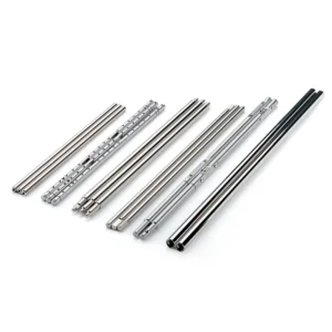
A fixed multi-hole bar offers a simple repeated pattern but requires the layout to be correct before fabrication. A modular guide assembly may allow selected guides to be installed or replaced separately, but introduces interfaces, locks, and spare parts that must be defined. A split-body arrangement may simplify cable installation, yet its joints and covers can affect appearance and service access. These are procurement directions to compare; availability depends on the proposed ESANG configuration.
Decide How Each Cable Enters and Leaves the Unit
The installation sequence determines whether the assembly needs closed through-holes, open slots, split guides, removable inserts, or another offered cable path. Ask these questions before selecting a guide:
- Will bare cable be threaded before the spacer body is fixed?
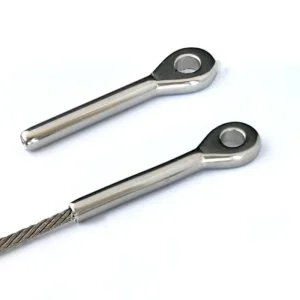
- Must a swaged end, threaded stud, ferrule, or other terminal pass through the guide?
- Can one cable be removed later without releasing all other rows?
- Does the guide need a sleeve, grommet, or replaceable contact surface?
- Which edges are factory finished, and which site cuts or holes need finishing?
An opening sized only for bare cable can block a preassembled fitting. An unnecessarily large opening can leave a visibly loose interface. A removable guide can improve service access only when its retaining part remains reachable after the assembly is mounted.
Match Body Length and Stiffness to the Number of Rows
More cable rows usually mean a longer pattern or closer openings. Both affect the spacer body. Request the proposed profile, overall length, wall or solid section where relevant, end distance, guide spacing, and top and bottom restraint. Do not compare assemblies by row count alone.
A body that is sufficiently stiff for a short three-row module may not behave the same when lengthened or heavily perforated. Visible bow, twist, difficult cable threading, and shifted centerlines are possible mismatch consequences. If multiple modules are stacked, the joint, alignment method, cumulative tolerance, and visual seam should be shown.
The top and bottom interfaces should be located from finished surfaces. State whether the assembly attaches beneath a top rail, between top and bottom rails, to a base plate, or to another defined frame component. Included brackets, caps, end plates, screws, and anchors must be listed instead of assumed.
Treat Adjustable Guides and Locks as Assembly Components
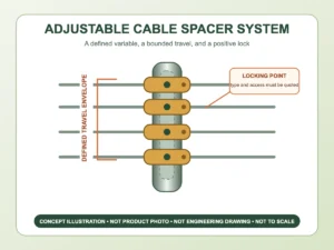
If the requested assembly includes movable guides or a position-adjustable body, specify what adjusts, the usable travel, and how every position is retained. The lock may be shared across a linked group or applied to each guide; those designs have different setup time and service implications.
Confirm tightening access, final engagement, sequence, replacement parts, and whether settings are made in the factory or on site. Adjustment is bounded by the body edges, adjacent guides, fastener access, and the approved cable pattern. It should not be described as universal or used to compensate for an unknown railing height, unlimited row spacing, or a structurally unverified bay.
Separate Level, Stair, and Transition Assemblies
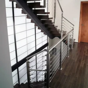
For a level run, define the vertical assembly body and horizontal cable centerlines from common datums. For a stair run, provide actual rise and run or a verified angle, cable direction, body orientation, top and bottom receiving faces, and the required first/last row positions. A stair assembly may need a different guide angle, end preparation, or mounting bracket even when the cable count matches a level unit.
At a landing or direction change, identify where one assembly ends and the next begins. Do not force level and sloped patterns into one generic module. A poorly defined transition can create abrupt cable bends, crossed lines, inaccessible locks, or a guide too close to an end connection.
Keep the Assembly Inside the Railing-System Boundary
A multi-cable spacer assembly guides and organizes the infill. It is not automatically a terminal post, cable tensioner, structural intermediate post, top-rail support, or anchor. The terminal and corner posts, structural frame, top rail, cable terminals, tensioning hardware, and anchorage remain separate responsibilities.
Post-to-post span and assembly placement must come from the complete project layout. Adding more cable guides to one assembly does not approve a longer bay. The responsible designer or project team should review cable tension, cable and spacer spacing, frame stiffness, opening limits, and local requirements together. The quotation should not be read as approval of the installed railing system.
Compare the Complete Bill of Material
| Assembly decision | Input van de koper | Quotation should list | Mismatch consequence |
|---|---|---|---|
| Pattern | Cable count, centers, datums, level/stair | Assembly drawing, row schedule, revision | Cable rows do not align with posts or boundaries |
| Guide system | Cable/fitting sizes and installation sequence | Hole, slot, guide, sleeve/insert, lock, spare parts | Terminals cannot pass or one cable cannot be serviced |
| Body | Clear height, top/bottom interfaces, required service access | Profile, length, section, end treatment, joints | Assembly bows, twists, or conflicts with the frame |
| Montage | Receiving surfaces, access, substrate or frame details | Included brackets, plates, caps, screws, anchors; exclusions | Missing parts or inaccessible fasteners stop installation |
| Delivery state | Factory/site work, quantity, exposure, finish, packaging | Preassembled/loose state, offered material/finish, labels, templates | Quotes hide different labor and component scopes |
A proposed package may include only the spacer body and guides, or it may itemize additional locks, brackets, fasteners, and templates. Cables, terminals, tensioners, structural posts, rails, anchors, installation, and compliance review are not included unless the quotation expressly lists them. Requested materials, finishes, cable counts, and assembly formats remain subject to the offered configuration.
Plan Factory Assembly and Field Work Together
Ask whether guides are installed and set before shipment, packed as labeled loose parts, or partly assembled for final site adjustment. If field cutting or drilling is expected, define the permitted operations, datum, template, tooling, edge finishing, cleaning, and inspection. If no site machining is available, state that at inquiry so the proposed unit can be reviewed as a finished assembly.
For replacement work, send front, side, and end photos with a ruler; count every cable row; record all centerlines; and show how the existing unit opens or attaches. A matching appearance does not prove the same guide size, lock, service sequence, or mounting interface.
Send a Pattern, Not Just a Quantity
Start with a marked elevation or sketch, cable row count and spacing, cable and terminal dimensions, level or stair geometry, body length, top and bottom interfaces, main-post spacing, proposed assembly stations, project exposure, finish request, estimated quantity, and preferred delivery state.
Before fabrication, freeze the assembly drawing, body profile and length, guide and cable passage details, locks, end connections, material and finish, factory/site split, included and excluded parts, quantities by pattern, spare-part request, packaging labels, and revision. That record makes multi-cable procurement repeatable without claiming that one assembly fits every railing.