A base plate that looks correctly sized on a shop drawing can still fail to land on its anchors if the hole pattern and the anchor layout were set from different reference points. The mismatch rarely shows up until the template is already embedded or the plate is already fabricated, which is why the coordination has to happen on paper first. The question is not whether the plate and the anchors are each individually correct, but whether they were drawn, dimensioned, and toleranced against the same reference system.
Where base-plate and anchor layouts must share one datum
A base-plate hole pattern and an anchor layout can each be dimensionally correct on their own drawings and still fail to align, because each was measured from a different reference point. The base-plate fabricator may dimension holes from the plate’s own centerline or edge, while the anchor layout may be set out from a building grid line, a slab edge, or a previously placed embed. If those two reference systems are not tied to one controlling datum, the error does not show up as a drawing conflict; it shows up as a physical mismatch in the field, after the plate has been fabricated and the anchors have been set.
This is why post centerlines, base-plate dimensions, and the anchor layout need to be resolved against a single datum before either the template or the plate is released for fabrication. Where the datum is the post centerline itself, the hole pattern and the anchor spacing can both be derived symmetrically from that center, which tends to simplify verification. Where the datum is instead a grid line or slab reference offset from the post location, every dimension carries an added translation step, and any rounding or drafting inconsistency in that translation becomes a fixed error in either the template or the plate.
The practical consequence is that “correct to the drawing” is not the same as “correct to the installed condition” unless the drawing itself ties both components to one shared reference. A base-plate shop drawing that shows hole spacing in isolation, without referencing the same datum used for the anchor setout, leaves the coordination step undone rather than completed. Reviewers should treat the datum statement as the first thing to confirm, not an assumption to leave implicit, because every downstream check on hole diameter, spacing, and orientation depends on both items having been measured from the same point of origin.
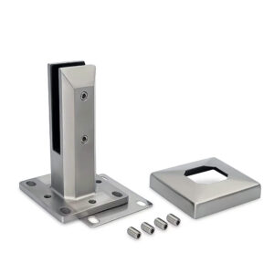
Where a project involves voetplaten voor opbouwmontage, the datum question also determines how the plate sits relative to the finished surface and the embedded or surface-fixed anchor layout beneath it, which affects how any later field check is interpreted. If the datum is unclear, a field measurement that shows the plate “slightly off” the anchors cannot be resolved without first knowing which component’s drawing is authoritative.
Hole diameter, spacing, orientation, and washer interfaces
| Interface | Coordination check | Beslissingsgrens |
|---|---|---|
| Hole diameter | Show the base-plate hole diameter with the anchor layout in the same coordinated drawing set. | On-site enlargement can affect bearing, washer coverage, finish, alignment, and the reviewed load path, so it requires explicit project acceptance. |
| Hole spacing | Match the fabricated base-plate spacing to the anchor template before batch production. | Do not rely on installer adjustment to absorb an unallocated mismatch. |
| Pattern orientation | Tie the hole-pattern orientation to the controlling datum and post centerlines. | If correction would require slotting or enlargement, obtain explicit project acceptance. |
| Washer interface | Check washer coverage against the hole diameter and any proposed slot or enlargement. | Washer coverage is one affected interface; it does not by itself establish acceptance of a field modification. |
Once a shared datum is established, the geometric details of the hole pattern itself become the next coordination layer. Hole diameter, spacing, and orientation are three separate variables, and a match on one does not confirm a match on the others. A base plate can have the correct number of holes at the correct spacing but rotated relative to the anchor layout, which produces a pattern that appears compatible until the plate is actually offered up to the anchors. Orientation errors are particularly easy to miss on a drawing review because they do not change any dimension value; they change only the relationship between the pattern and the post centerline or the structure’s edge.
Hole diameter carries a different kind of consequence. The diameter is not simply a clearance question; it also determines how much the washer can bear against the plate surface once the anchor is tightened. A washer is sized to transfer load across a defined contact area, and if the hole is enlarged beyond what the washer was selected for, part of that bearing area is lost even though the fastener itself still fits. This is a case where a change in one dimension changes the function of an adjoining component that was not itself modified.
Where these interfaces are reviewed together rather than separately, mismatches surface before fabrication rather than after. Where they are reviewed in isolation, each individual check can pass while the assembled condition still fails.
Fabrication and concrete setout tolerances to coordinate
Every dimension in a base-plate and anchor assembly carries some tolerance, and the question that matters for coordination is not whether tolerance exists but how it is distributed across the stages that contribute it. Concrete setout tolerance, drilling tolerance, plate manufacturing tolerance, and post plumb tolerance each contribute independently to the final fit, and if a project’s drawings assign no explicit allocation among them, the unaccounted variation has to be absorbed somewhere in the field.
Where tolerance is allocated deliberately across these four sources, each stage carries a known share of the acceptable variation, and the final installer’s adjustment becomes a check rather than a correction. Where no allocation is made, the practical default is that whatever variation accumulated upstream gets pushed onto the installer to resolve at the post, often by means that were never reviewed against the load path. This distinction matters because the four sources behave differently: concrete setout tolerance is set before the plate exists, drilling tolerance depends on the equipment and method used to place anchors, plate manufacturing tolerance depends on the fabrication process producing the base plate, and post plumb tolerance is a function of the erection sequence itself. A project that treats these as one undifferentiated “installation tolerance” loses the ability to identify which stage is responsible when a mismatch occurs.
The practical implication for a buyer or specifier is that tolerance allocation needs to be a stated decision, not an assumption. If the project drawings are silent on how tolerance is divided, the question to raise is which stage absorbs the variation when the others are within their own limits, and whether that absorption is accounted for in the base-plate hole sizing itself or left entirely to field judgment.
Slotting or field modification risks requiring approval
When a base plate does not land cleanly on its anchors, the available field responses are usually to slot or enlarge one or more holes so the plate can be shifted into position. This fix addresses the immediate placement problem, but it changes several things at once that were set during the original design review. Bearing area changes, because the fastener now contacts the hole at a different point and the enlarged or slotted opening changes how the washer sits against the plate. Finish can be affected at the cut or drilled edge, depending on the material and the method used. Alignment of the plate relative to the post may shift as a side effect of the correction itself. Most significantly, the load path that was reviewed and accepted for the original hole pattern is no longer the load path that exists after the modification.
None of these consequences are necessarily disqualifying on their own, but they are consequences, not neutral corrections, and that is why slotting or enlarging holes in the field needs explicit project acceptance rather than being treated as an installer’s routine adjustment. The distinction is between a tolerance that was anticipated and allocated in advance, and a modification made reactively to solve a fit problem that was not anticipated. The first is a planned part of the assembly; the second changes the assembly after its load path was reviewed, and the people who approved that review were not necessarily the people making the field decision.
Where a project’s specification or shop drawing review process requires sign-off on field changes, this is the category of change that should trigger it, because the people best positioned to judge whether a modified hole still meets the original design intent are the same people who reviewed the original hole pattern, not the installer working to close out the post.
Drawing checks before templates and posts are released
Before an anchor template is released for use and before base plates are released for batch fabrication, the template and the plate need to be checked against each other as a paired set rather than each checked independently against its own drawing. A template that matches its own layout drawing and a plate that matches its own fabrication drawing can still fail to pair correctly if either drawing was produced, revised, or interpreted independently of the other. Checking them as a pair means confirming that the same datum, the same hole diameter, the same spacing, and the same orientation appear on both documents before either is committed to production.
This pairing check matters most at the release point because it is the last step before the cost of an error changes category. Before release, a mismatch is a drawing correction. After the template has been used to set anchors and the plates have been fabricated in batch, the same mismatch becomes a field problem requiring the kind of modification that carries its own approval requirements. A shop drawing checklist that treats the template and the base plate as separate line items, each individually approved, can miss a pairing error that only appears when the two documents are laid against each other directly.
Where a project’s documentation already separates post centerlines, plate dimensions, hole geometry, and the controlling datum onto one coordinated drawing set, this pairing check becomes a verification step rather than a discovery process, because the same reference information governs both the template and the plate. Where that coordination has not been done, the pairing check is the point at which the gap becomes visible, and it is better found there than after fabrication and anchor placement have both proceeded on separate assumptions. For a project sourcing verankeringssystemen en base plates as coordinated components, this is the review stage that determines whether the supplied hardware will fit the field condition as drawn, rather than requiring correction after delivery.
Veelgestelde vragen
V: What information should be frozen before the anchor template and railing posts are released?
A: Freeze the post centerlines, base-plate dimensions, hole diameter and spacing, pattern orientation, and controlling datum in one coordinated drawing set. Use that same information to check both the anchor template and fabricated base plate before batch production.
V: What should the project team do if the base-plate holes do not align with the installed anchors?
A: Treat the mismatch as a project coordination issue rather than assigning it automatically to installer adjustment. Compare the installed layout and fabricated plate against the controlling datum, document the direction and size of the mismatch, and obtain explicit project acceptance for any proposed correction.
V: Can base-plate holes be slotted or enlarged on site to make the anchors fit?
A: Only with explicit project acceptance. The review should consider bearing, washer coverage, finish, alignment, and the previously reviewed load path before the modification proceeds.
V: How should installation adjustment be planned when several tolerances affect alignment?
A: Allocate the available tolerance among concrete setout, drilling, plate manufacture, and post plumb before release. Do not assume the installer can absorb every accumulated variation at the final installation step.
V: What details should accompany a request to approve a hole-pattern correction?
A: Show the controlling datum, post centerline, actual and intended hole geometry, pattern orientation, washer coverage, and the proposed slotting or enlargement. This gives the project reviewer the information needed to assess the affected interfaces rather than judging the correction from hole size alone.