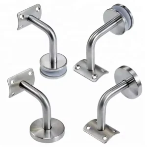
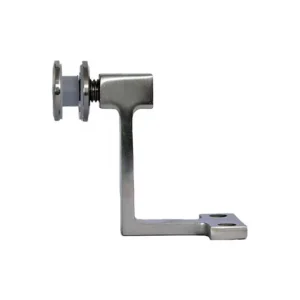
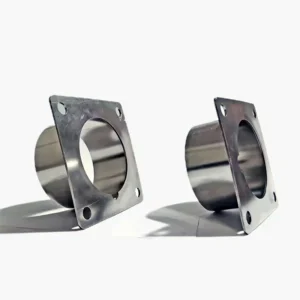
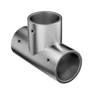
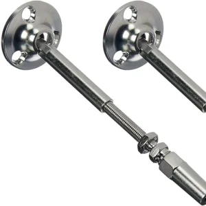
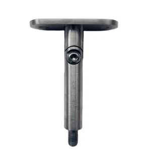
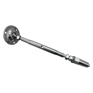
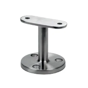
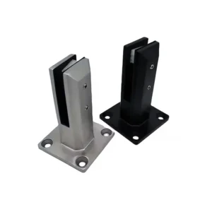
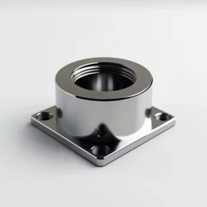
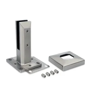
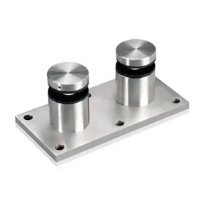
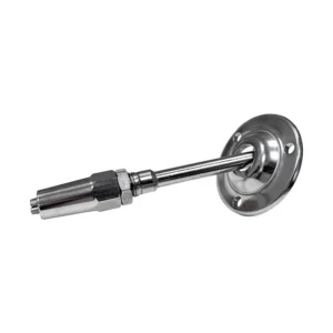
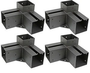
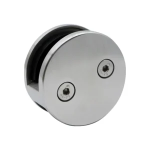
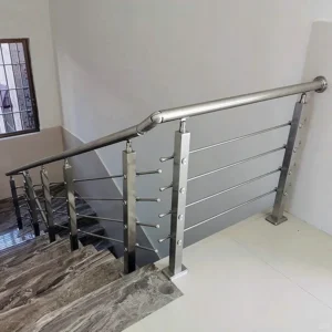
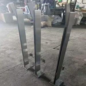
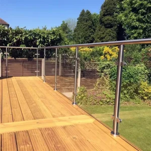
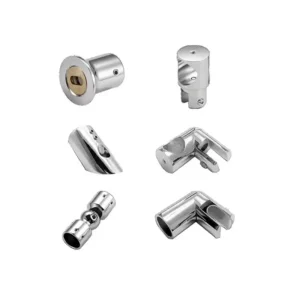
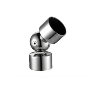
Post clamp brackets connect an infill, panel or rail-side component to a post through a defined clamp-and-mount interface. The word “clamp” describes only part of the connection: it does not prove that the bracket wraps around the post, avoids every drilled hole, leaves the clamped component unmarked, or gives the complete railing a verified load rating. Start with a photo or sketch, the post section, the clamped component and approximate quantity.
Define what is clamped and what is mounted
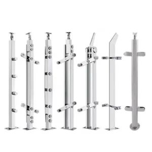
A useful drawing separates two interfaces. The clamp side may capture glass, another panel or a prepared rail-side element between contact faces. The post side may use a flat flange, hole pattern, stud, welded feature, threaded insert, wrap-around piece or another connection. Neither side can be selected from the product title alone.
State the clamped component’s material, thickness, build-up, edge condition and whether it has holes. For glazing, give the glass make-up and processed dimensions rather than thickness alone. For the post, give round diameter or square width, wall thickness, corner radius where relevant, and access to the hollow interior.

Clamp-on does not automatically mean no drilling
Some compression clamps may be designed to hold an unperforated panel; other clamps require a hole, locating pin or prepared notch. Even if the clamped panel is not drilled, the bracket still needs a defined connection to the post. That post-side connection may require holes, inserts, through-bolts, welding or a separately specified wrap-around clamp.
Therefore record “panel drilling” and “post drilling” as two separate decisions. If a non-drilled panel is required, say so explicitly and require the proposed clamp to identify its contact pads, retention method, edge clearances and compatible panel build-up. Do not describe the solution as automatically damage-free: contact pressure, grit, movement, incompatible gaskets or incorrect tightening can still mark or damage a surface.
Match the bearing faces and wall thickness
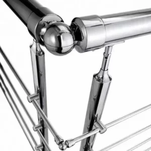
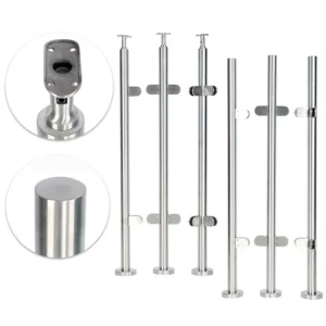
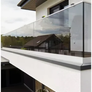
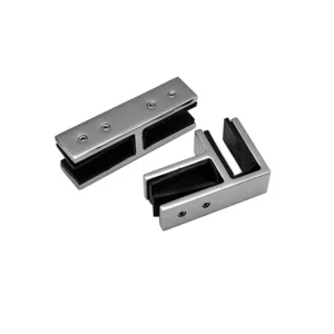
The clamp’s contact area, pad or gasket and fastener position must suit the captured component. Too little contact can concentrate pressure; excessive clearance can permit slip or rotation. A photograph can show that pads or contact pieces are visible, but it cannot prove their material, thickness or compatibility.
On the post side, a thin hollow wall can distort under local bolt or clamp force. The proposed configuration should state whether it needs a backing plate, internal sleeve, rivet nut, welded boss, through-bolt or other prepared interface. For round posts, confirm the saddle or adapter radius. For square posts, confirm the flat face, corner clearance and anti-rotation arrangement.
Keep panel retention, handrail support and barrier performance separate
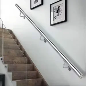
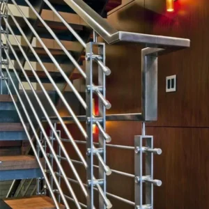
A clamp intended to retain an infill panel is not automatically a handrail bracket, and a small hardware item does not establish the performance of posts, rails, glass, anchors or the complete barrier. Identify the bracket’s exact component responsibility and include the adjacent system on the drawing. If a top rail or graspable handrail is also present, show its separate support and connection.
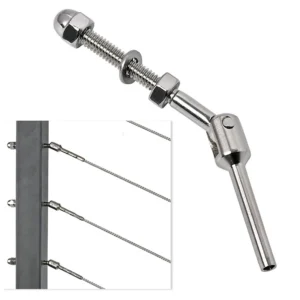
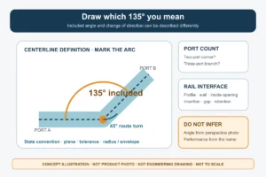
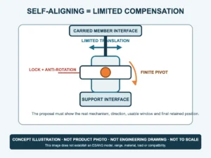
Where the joint can be adjusted, confirm whether the feature sets panel position, rail angle or post alignment. State the permitted range and locking method. Do not infer multi-angle service capability from a slotted hole or pivoting appearance.
Choose the retention route deliberately
| Route | Benodigde informatie | Boundary to record |
|---|---|---|
| Compression clamp on panel | Panel build-up, thickness, edge, pads and fastener setting | No panel drilling only if the exact proposed clamp states it |
| Pin or hole-assisted clamp | Hole/notch geometry, edge distance and processed dimensions | Panel preparation belongs in the approved drawing |
| Bracket bolted to post | Post section, wall, holes, backing/insert and access | Panel clamp does not remove post drilling responsibility |
| Bracket clamped around post | Post geometry, wrap/contact area, finish and anti-slip feature | Non-drilled post only when the quoted design explicitly provides it |
Control slip, rotation and tightening
Ask the proposed configuration to identify how the clamped part is prevented from sliding, how the bracket is prevented from rotating on the post, and how each fastener is accessed. The final setting may depend on pad compression, locating features, multiple fasteners or a positive pin. The required tightening instruction must come from the exact proposed joint; more torque is not a substitute for correct contact area or internal post support.
Divide factory and site work
The quotation should state whether it includes clamp body, pads/gaskets, pins, post-side fasteners, inserts, covers and any prepared post component. Factory work may include drilled or threaded features, welded bosses, bracket assembly or matched sets. Site work may include layout, post drilling, panel placement, setting, tightening, protection and final system inspection. These responsibilities should be visible before the panels and posts arrive on site.
Send these fields for a comparable proposal
For initial review, send the post section and wall thickness if known, clamped component type and thickness, drilled or non-drilled preference, bracket location, approximate quantity, exposure condition and photos or a sketch. Before order release, confirm panel build-up and edge details, pads/gaskets, hole or pin requirement, post-side interface, backing or insert, fasteners, anti-slip/anti-rotation method, setting range if any, included parts, factory/site split and project-specific structural or regulatory verification.
Send post and clamped-component details to WhatsApp: +86 185 6601 2949