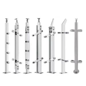
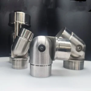
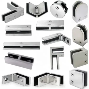
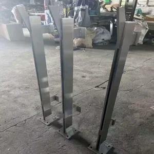
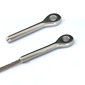
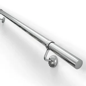
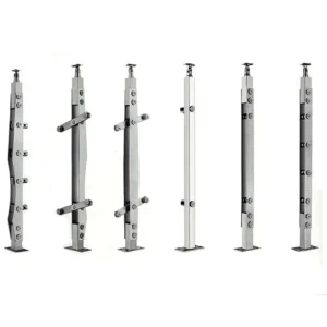
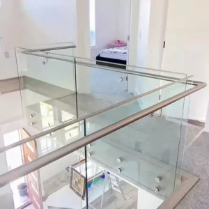
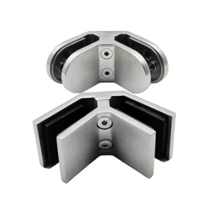
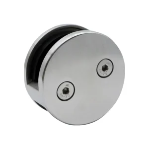
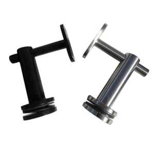
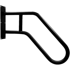
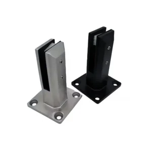
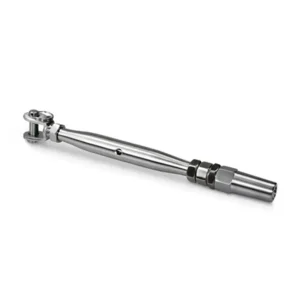
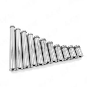
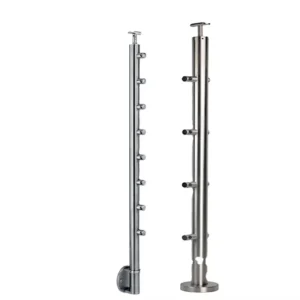
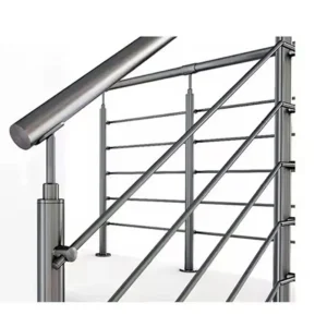
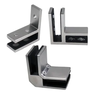
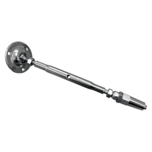
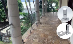
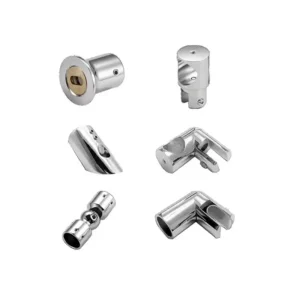
Flush mount wall brackets use low-profile mating plates to bring a removable component close to the wall with little visible stand-off. The public product photos show paired interlocking plates, not a complete handrail or guard assembly. For railing work, select this route only when the complete load path, positive retention and wall attachment are verified for the project. Send the component, wall and removal-access details to begin a configuration inquiry.
Ask about flush mount bracket pairs
Choose flush mounting for the interface—not for a name
A paired plate can suit a cover, removable trim or another component that needs a close wall line and a defined engagement direction. It is not automatically suitable for a graspable handrail, guard or barrier. Those applications can include lateral, uplift, pull-off and impact demands that must be addressed by the complete attachment and project design.
- Component role: identify exactly what the plate supports and whether it is decorative, removable, load-bearing or part of a regulated railing assembly.
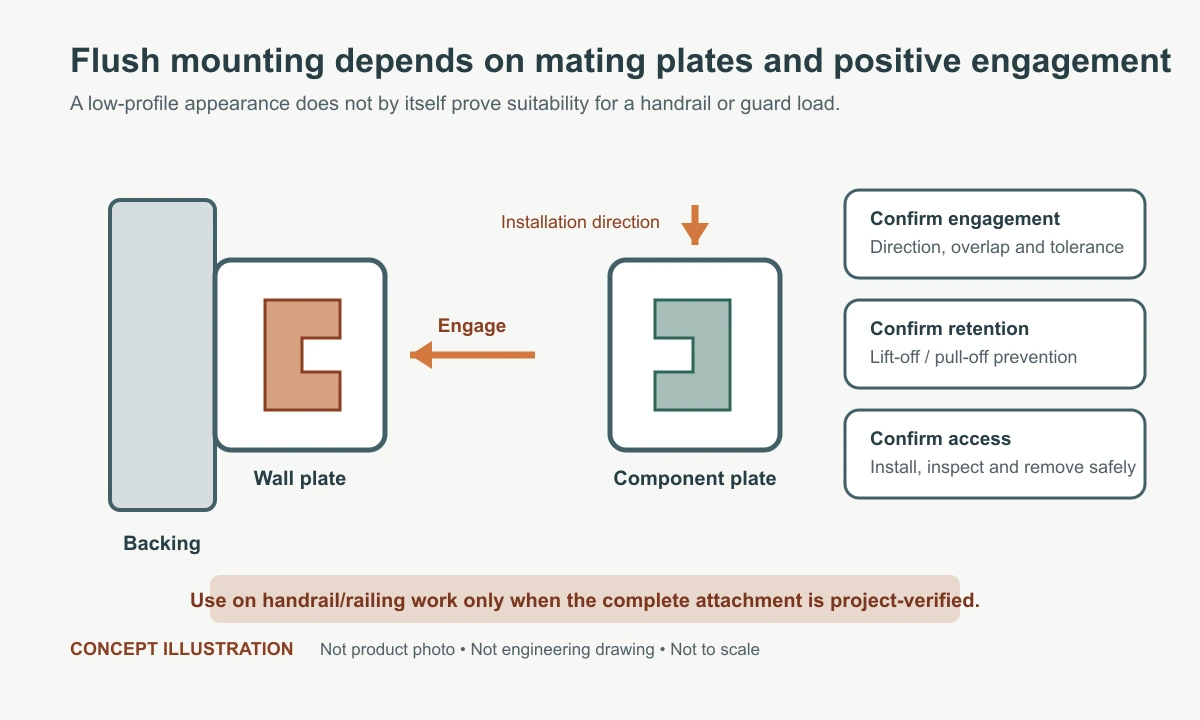
- Engagement direction: show the travel needed to join the two plates and confirm that ceilings, adjacent panels or rail ends do not block installation.
- Installed stand-off: state the permitted projection from the finished wall to the component face. “Flush” does not guarantee zero stand-off, and these paired plates provide no field adjustment unless the proposed design says so.
- Positive retention: state how lift-off, pull-off or accidental disengagement is prevented where the risk requires it.
- Service access: keep enough movement and tool access to inspect or remove the component without damaging finishes.

Two mating plates create one attachment
The wall plate and component plate must be treated as a matched pair. Compare their thickness, footprint, hole pattern, engagement overlap, manufacturing tolerance and installation direction together. Mixing visually similar halves can reduce engagement or prevent assembly. If the component can be lifted, vibrated or pulled away during use, the proposal must also identify the retention approach rather than relying on gravity by assumption.
Compact and larger forms are not interchangeable
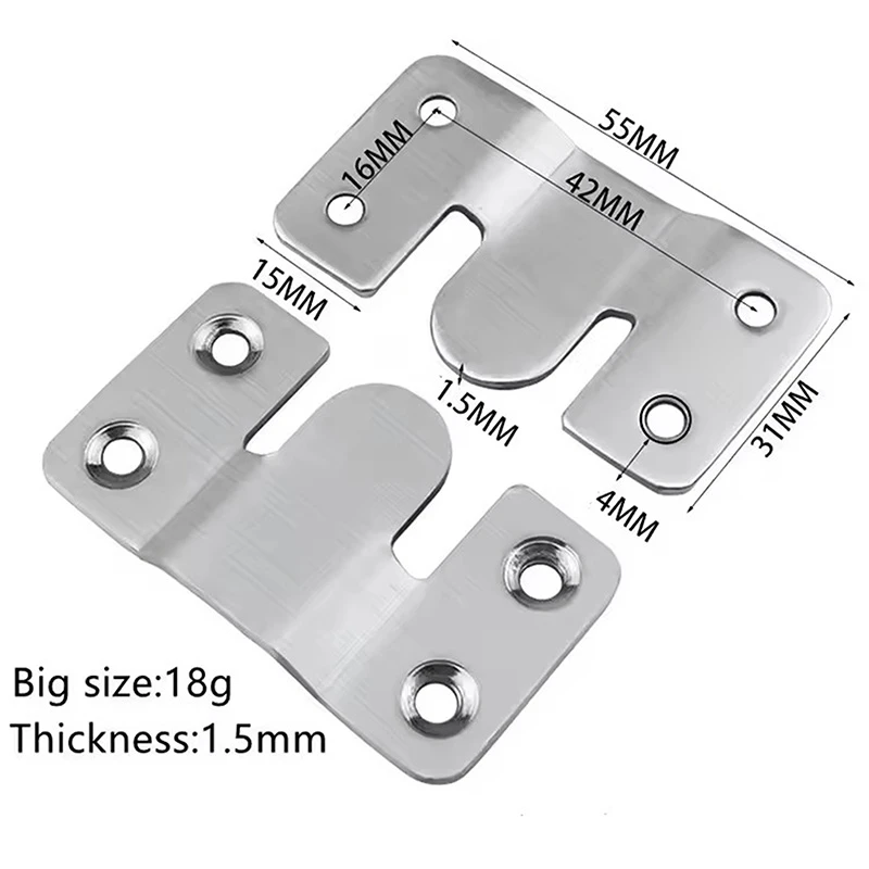
A larger plate may offer a different fixing footprint or engagement area, but size alone does not establish capacity. The available component edge distance, wall backing, fastener head seating and installation access can make the smaller or larger form unsuitable. Request a drawing for the exact proposed pair and compare the drawing—not the printed labels in a reference image.
Coordinate the wall and component fasteners
Wall side
Identify the load-bearing substrate behind the finished surface, available plate area, edge distances and drilling or through-bolt access. The responsible project party selects or approves anchors for the actual substrate and load case. A thin finish layer or hollow board is not structural backing unless the complete assembly is designed for it.
Component side
Provide the component material, thickness, internal reinforcement and available fastener length. Countersunk holes require compatible head geometry and seating; an incorrect head can stand proud and prevent the plates from mating. Confirm whether fasteners remain captive or accessible after engagement.
Handrail or railing use
If the plate pair is proposed for a handrail or railing component, provide the system role, governing loads, bracket or plate spacing, connection orientation and required approvals. The proposed design must address shear, pull-off, uplift/disengagement and the supporting wall; the flush appearance is not evidence of structural suitability.
Fields to freeze before production
| Field | Besluit | Common mismatch |
|---|---|---|
| Matched pair | Exact plate geometry, thickness and overlap | Similar-looking halves do not fully engage |
| Movement | Installation direction and required travel | Adjacent construction blocks assembly or removal |
| Retention | Method to resist unintended lift-off or pull-off | Gravity is assumed sufficient without review |
| Bevestigingsmiddelen | Head, diameter, length and substrate/component engagement | Fastener heads prevent the plates sitting flush |
Factory and site responsibilities
The factory proposal can define the matched plate pair, proposed material/finish, hole form, included fasteners requested for the component side and packaging. Site responsibility normally includes verifying backing and dimensions, selecting or approving wall anchors, setting out paired plates consistently, providing any required secondary retention and inspecting full engagement. The quote should record this split explicitly.
Start with the supported component and access path
Send a component drawing or photo, wall build-up, expected load or purpose, plate locations, installation direction, removal clearance, environment and quantity. If the application is a handrail or railing, also include load criteria and approval requirements. The returned proposal should identify exact plate geometry, proposed material/finish, included fasteners, retention assumptions, documentation and exclusions.