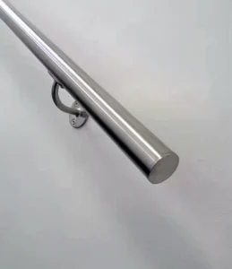
Beugels voor paalmontage
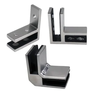
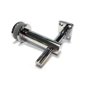

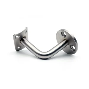
Beugels voor paalmontage
Match the post side and the rail side as one connection
A post-mount bracket has two interfaces: the post or clamp side and the supported handrail or rail side. Choosing only by post shape can still leave the wrong saddle, rail orientation or fixing method. Use the current product routes below to define the connection, then place the exact post section, rail profile, angle and included fasteners on the proposed drawing.
Discuss post-bracket options on WhatsApp
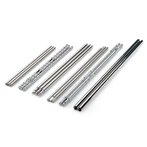
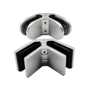
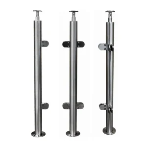
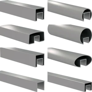
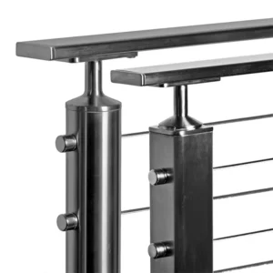
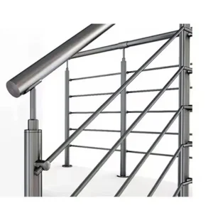
Two visible interface forms
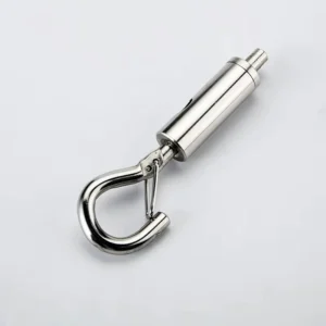
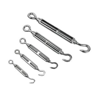
Five current product routes
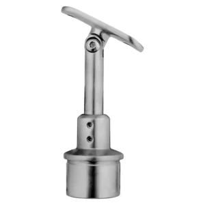
Use when the post-side interface must fit a curved post surface. Provide the actual post outside diameter and wall condition as well as the supported rail profile.
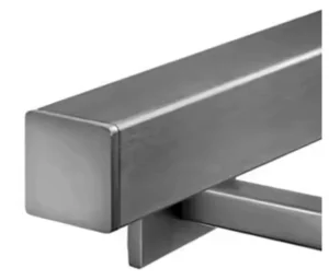
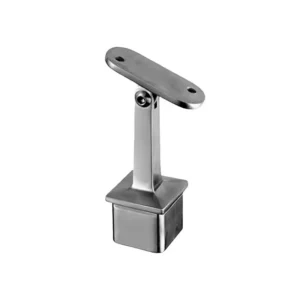
Use for a flat post face, including a square or separately confirmed rectangular section. Record face orientation, post size and where the rail axis sits relative to the post.
Use when the rail support needs a defined adjustment at the post. Confirm the adjustment axis and range, the final locking detail and whether installation access remains available.
Use for a route with planned non-straight or changing directions. Supply the actual plan and elevation angles; the product name does not prove unlimited axes or angle range.
Use when a clamp-style post connection is being considered instead of a welded or plate-fixed interface. Match post shape, contact surfaces, tightening access and protection of the finished post.
Define fit before finish
Interface — Minimum buyer input — Mismatch to avoid
Post — Cross-section, outside dimensions, wall thickness or backing, face orientation and fabrication state — A curved seat on a flat face, a flat plate on the wrong post face, or a fixing that cannot reach suitable structure.
Rail or handrail — Profile, outside and relevant inside dimensions, route direction and desired contact/saddle form — A visually similar bracket head that does not seat on or align with the actual rail.
Connection method — Welded, drilled/mechanical, clamped or another project-defined method — Buying a component that needs fabrication or access the installer cannot provide.
Angle and position — Plan/elevation angles, rail axis, height and any field adjustment required — Treating an adjustable joint as universal or omitting the final locked position.
Adjacent infill — Glass, cable, bar, panel or open-zone locations near the bracket — Collisions with clamps, cable holes, tensioning hardware or edge clearances.
Exposure — Location, moisture/chloride or chemical exposure, finish requirement and cleaning regime — Assuming a photographed surface or category name proves a suitable material/finish.
Bracket fit is not whole-system approval
The post, bracket, rail, fasteners, nearby infill and base connection act together. A bracket photo cannot establish post capacity, rail capacity or the performance of the installed railing. The project team should confirm the design actions, post and rail fabrication, bracket spacing, fastener detailing and applicable requirements for the complete assembly.
If welding is proposed, ask who supplies the final weld preparation and finish restoration. If a clamp or mechanical fixing is proposed, ask for contact geometry, included pads or fasteners, tightening access and any inspection requirement to be shown on the proposed configuration.
Ask for a quotation you can compare
• exact post-side and rail-side geometry, not only “round” or “square”;
• fixed, adjustable, multi-angle or clamp connection and its final locking/fixing method;
• proposed material grade, finish and visible surface direction;
• included bracket pieces, pads and loose fasteners, plus explicit exclusions;
• fabrication or site work required before installation;
• dimensions and project decisions still open before production.
A photo with two or three marked dimensions is enough to start route selection. A production-ready match still needs the final post and rail data.
Gerelateerde berichten:
Vlakke, schuine of van schuin naar vlak overgaande gaaspanelen: welke geometrie hoort bij elk leuningtraject?
Choose between level, raked, and raked-to-level mesh panel geometry by railing run, pattern orientation, interfaces, and project drawings.
How to Specify Internal Sleeves and Splice Locks for Handrail Tubes
Specify handrail sleeves and splice locks by the actual tube interior, required retention and installation access so the connector can fit and be secured.
Waar moeten de verbindingen en steunen van leuningen bij lange trajecten worden geplaatst?
Zorg ervoor dat verbindingspunten worden voorzien van steunen, overgangen en toegangsmogelijkheden voor montage, zodat de breekpunten voor het transport ook fungeren als gedocumenteerde verbindingen in de geïnstalleerde leuning.
Continuous Handrails and Joints: A Project Specification Guide
Connect the usable rail path with joint function, supports, movement and transport modules before issuing a continuous handrail specification.
Surface-Mount Handrail RFQ: Drawings and Project Data to Send
Send coordinated run drawings, substrate details, finish references and scope requirements so surface-mount handrail quotes can be compared meaningfully.
Achteraf aanbrengen van opbouwleuningen: checklist voor het terreinonderzoek
Leg de bestaande ondergrond, de toestand van de randen, de afwerkingen, verborgen leidingen en installaties, de toegankelijkheid, de geometrie en de omvang van de reparatiewerkzaamheden vast voordat met de fabricage voor de aanpassing wordt begonnen.
Esangs projecten

Esang's certificaat
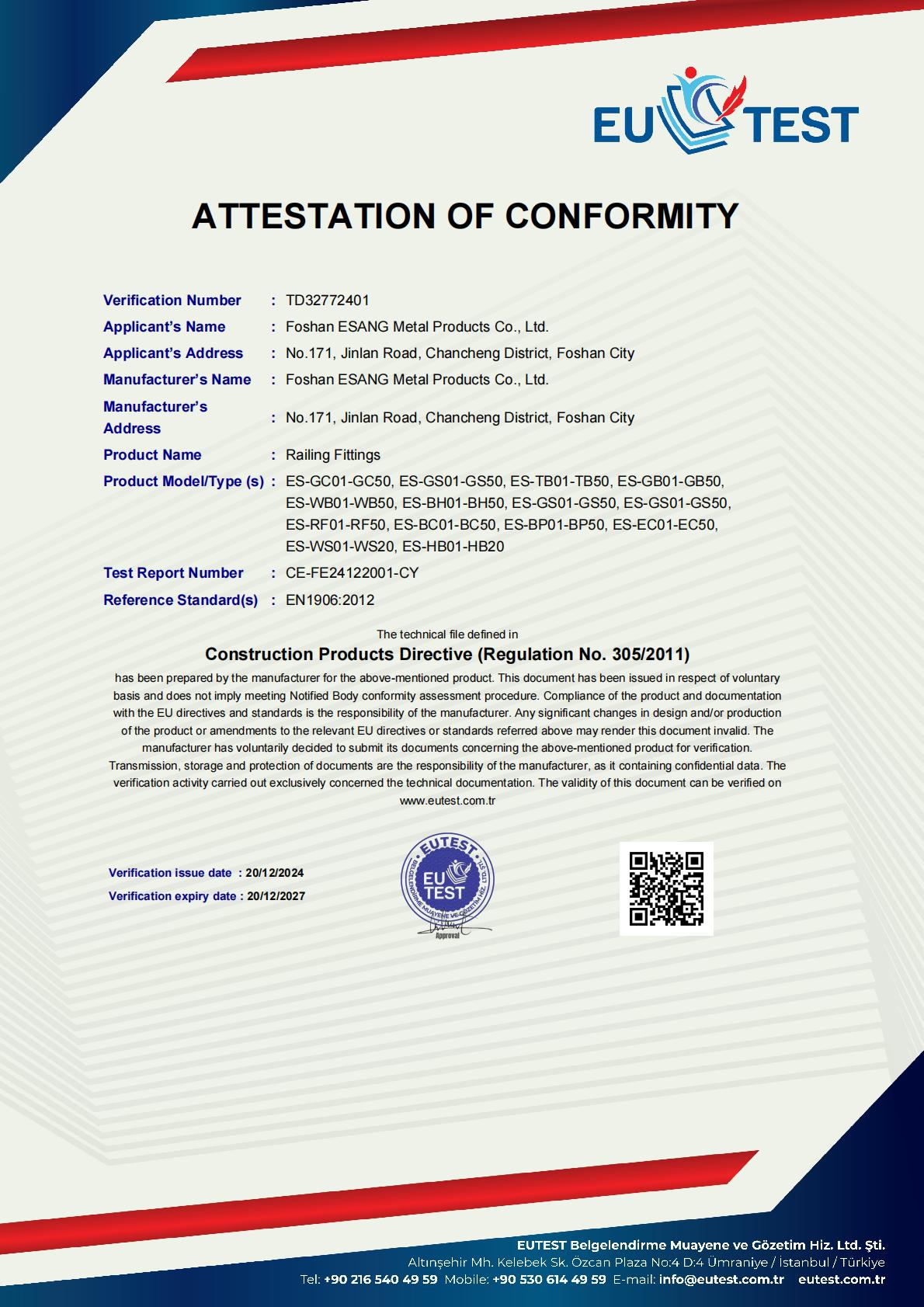
Foshan ESANG Metal Products onderhoudt met trots CE-certificering (Verificatienummer TD32772401) onder de Richtlijn bouwproducten (Verordening nr. 305/2011), waarmee we onze toewijding aan de hoogste Europese veiligheids- en kwaliteitsnormen bevestigen.
Gecertificeerd Assortiment:
Ons uitgebreide assortiment railingbeslag - inclusief glasklemmen, spanners, beugels, muurbevestigingen, basischoenen, leuningbeslag, kabelbeslag en staanderonderdelen - voldoet aan de volgende eisen EN1906:2012 normen, zodat de structurele integriteit en betrouwbaarheid van de prestaties in alle installaties gewaarborgd zijn.
Wat dit betekent voor je project:
✓ Volledige naleving van regelgeving voor Europese en internationale markten
✓ Onafhankelijk geverifieerde veiligheids- en duurzaamheidsprestaties
✓ Documentatie-ondersteuning voor architecturale specificaties
Gemoedsrust dankzij kwaliteitsgarantie van derden
Certificering geldig tot 2027 | Testrapport: CE-FE24122001-CY
Esangs projecten

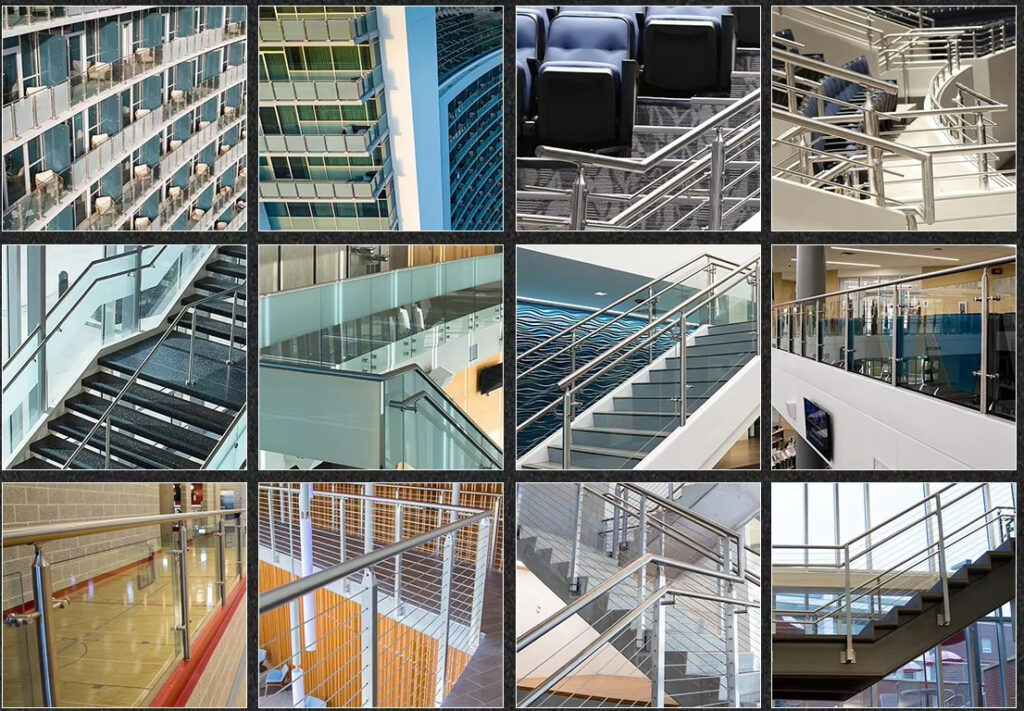
Referentieproducten