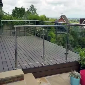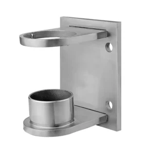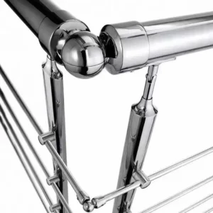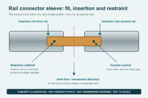
Keep the Cable Pattern Controlled Between Structural Posts
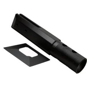
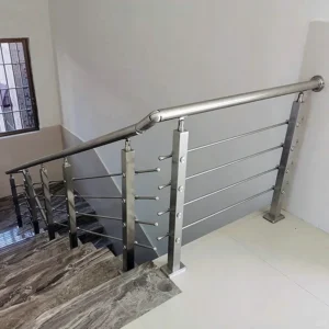
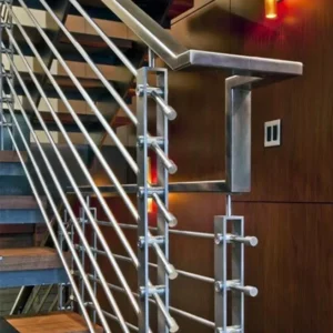
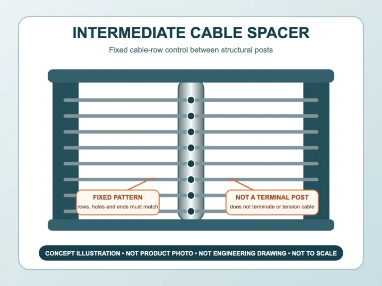
An intermediate cable spacer is a slim, fixed-pattern member placed inside a railing bay. Its job is to keep several horizontal cable rows on their intended centerlines and limit local separation between adjacent rows. It is not a terminal post, it does not tension the cables, and it does not make a wider post layout structurally acceptable.
This option suits a buyer who already has a defined level or stair cable schedule and needs a repeatable spacer station between the main posts. The key purchase is the complete match: row count and pitch, cable passage, bar length and stiffness, top and bottom interfaces, exposure, and the position of every spacer station within the approved railing layout.
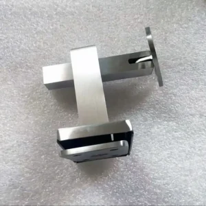
You can begin with a photo and one known dimension. Before fabrication, the drawing or quotation should freeze the remaining interfaces rather than treating a similar-looking bar as interchangeable.

Choose the Fixed Intermediate Role Deliberately
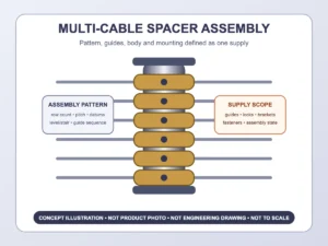
Use this product direction when a single bar at a planned station will guide a known set of cable rows. If the guide positions or mounting points must move after installation, ask about an adjustable spacer system instead. If the required bar body is unusually long, specify an extended-length spacer and review stiffness. If the purchase needs several guides, brackets, or pre-arranged parts as one serviceable unit, define it as a multi-cable spacer assembly.
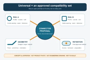
Those names describe different procurement problems. They should not be collapsed into one “universal spacer,” because the hole pattern, end connections, field sequence, and replacement parts can differ.
Build the Spacer Schedule from the Actual Bay
Cable count and centerlines
State the number of cable rows, the center-to-center pattern, and the distances from the first and last cable centerlines to the finished top and bottom boundaries. Also identify the cable diameter and construction. A drawing based only on total railing height can put the first hole too high, leave the last row too low, or create a pattern that no longer aligns with the holes through the main posts.
If several railing elevations use different row counts, do not order them under one undifferentiated part description. Give each pattern its own drawing revision, quantity, and location reference.
Level runs and stair runs are different
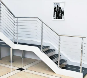
A level spacer normally follows horizontal cable rows through a vertical bar. A stair spacer must match the actual stair pitch, cable direction, finished rail boundaries, and mounting orientation. Ask the quotation to state whether the offered part is drilled for a level run, prepared for a defined stair angle, or supplied for controlled field work.
Sending only a nominal stair angle is risky when site rise and run, post faces, top-rail position, or floor finishes are not frozen. A level hole pattern rotated on site may move the cable exits toward an edge, misalign the rows, or leave the end faces unable to seat against their receiving surfaces.
Specify the Cable Passage, Not Just the Cable Diameter
The bare cable diameter is only one input. Confirm whether the installer must pass a threaded stud, swaged terminal, protective sleeve, ferrule, or other preassembled component through the spacer. The largest passing diameter and the installation sequence determine whether a simple through-hole is workable.
- Hole position: record every centerline from a stable datum so the spacer, post holes, and cable schedule can be compared on the same drawing.
- Hole or guide form: ask the proposed configuration to identify a plain hole, slot, removable guide, split insert, or other offered detail; do not infer the internal arrangement from a concept image.
- Sleeves or grommets: request them when the project design needs isolation or a finished cable contact surface, and require the quotation to say whether they are included, separate, or not offered.
- Edge condition: hole edges, cut ends, and field-drilled surfaces need an agreed finish. A burr or sharp transition can mark cable, obstruct threading, or damage an insert.
- Remaining material around openings: row pitch, hole size, bar width, wall thickness, and end distance interact. Moving one field without reviewing the others can weaken or distort the spacer body.
Match Bar Length, Stiffness, and End Connections
Overall length should be measured between defined finished interfaces—not guessed from guard height. Show whether the top end sits beneath a top rail, enters a bracket, stops short of the rail, or uses another connection. Show the same for the bottom end: bottom rail, base plate, deck-side connection, or another receiving part.
The profile, wall or solid section, unsupported length, cable-hole pattern, and end restraint affect how easily the bar can bow or twist while the cables are installed and tensioned. “Same height” does not mean “same stiffness.” The quotation should therefore identify the proposed body profile, overall or cut length, end preparation, and attachment parts rather than offering length alone.
If field trimming is planned, define the trim allowance, which end may be cut, how the new end is finished, whether any holes or threads can be affected, and who supplies the drilling template and tools. Cutting first and deciding the interface later can remove a mounting feature or shift every cable centerline.
Keep the Structural Boundary Clear
The terminal posts, corner posts, structural intermediate posts, top rail or frame, anchorage, cable terminals, and tensioners carry responsibilities that the spacer does not automatically assume. A fixed intermediate spacer organizes the infill inside that system. It should not be counted as an end anchor for cable tension or as structural support for the top rail unless a project-specific design explicitly verifies that different role.
Post-to-post distance, cable tension, cable spacing, spacer-station spacing, frame stiffness, and local opening requirements must be reviewed together by the responsible project team. A spacer can reduce local cable deflection; it cannot by itself approve the structural bay or guarantee compliance.
Define the Supply Boundary Before Comparing Prices
| Quotation field | What the buyer should provide | What the proposed supply should state | Typical mismatch consequence |
|---|---|---|---|
| Cable schedule | Row count, centers, first/last row, level or stair | Hole or guide schedule and drawing revision | Rows miss the post pattern or finished boundaries |
| Cable passage | Cable and largest preassembled part | Opening basis, guides, sleeves, or inserts included | Cable cannot be threaded or sits loosely at the guide |
| Body and ends | Finished receiving surfaces and measured length | Profile, length, end treatment, attachment pieces | Bar does not reach, seat, or remain aligned |
| Bay placement | Post spacing and marked spacer stations | Quantity tied to each elevation or bay type | Incomplete bill of materials or inconsistent support |
| Scope | Requested material/finish, exposure, packaging, site work | Offered material and finish; included/excluded guides, brackets, fasteners, templates | Quotes appear equal but require different site work |
Material grade, finish, cut-to-length service, loose lengths, special packaging, templates, guides, sleeves, brackets, and fasteners are requests to be confirmed in the proposed configuration. They are not implied by the product name or illustration. Cables, tensioners, terminals, structural posts, top rail, anchors, installation, and project approval are also separate unless itemized.
Send the Minimum Information to Start
- a railing elevation, marked photo, or hand sketch with one known dimension;
- level or stair layout, including actual stair rise/run or angle if known;
- cable row count, pitch, diameter, construction, and any preattached terminal;
- top and bottom receiving interfaces plus the intended spacer stations in each bay;
- estimated quantity, project location, exposure, and requested appearance; and
- whether ESANG should review a replacement match, a trial quantity, or a new project batch.
The inquiry can start while some dimensions remain open. Before fabrication, the agreed record should freeze the bar profile and length, cable and hole schedule, stair orientation where applicable, end connections, material and finish, included hardware, site work, quantity, and drawing revision.