Adjustable post brackets are setting devices for a defined post-to-rail or post-to-support interface. They are useful when installation geometry must be aligned within a controlled range, but “adjustable” does not mean universal, infinitely movable or suitable for movement during service. Start with a photo or sketch, the post section, the supported rail section and the angle or offset that must be corrected.
Discuss adjustable post brackets on WhatsApp: +86 185 6601 2949
Name the adjustment that the site actually needs
Height, rail slope, yaw around the post and bracket projection are different adjustments. A pivot that changes rail slope may not correct a lateral offset; a slotted plate that changes height may not rotate to follow a stair. State each required movement separately and identify its direction on a sketch.
- Single-plane tilt: commonly considered where a rail needs to follow a slope. Confirm the pivot plane and whether the post and rail remain centred.
- Height or slot adjustment: useful for setting a level or centreline within a limited travel. Confirm slot length, remaining edge distance and how the final position is clamped.
- Rotational setting: useful only when the assembly and adjacent components can clear the required position. Confirm the rotation axis and interference envelope.
- Projection or stand-off: changes the moment applied to the bracket and post. Do not substitute an extended arm for a standard support without project review.
Adjustment range must be confirmed, not inferred
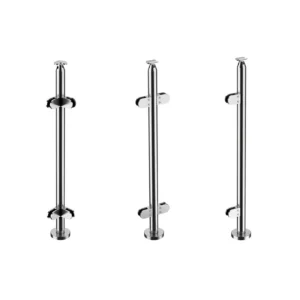
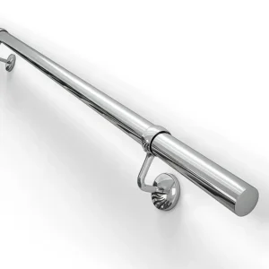
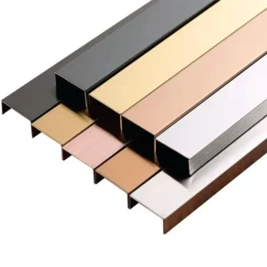
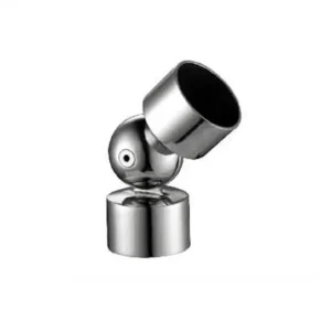
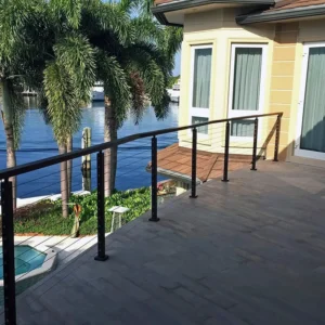
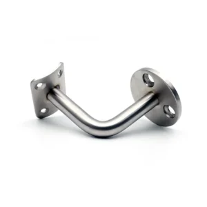
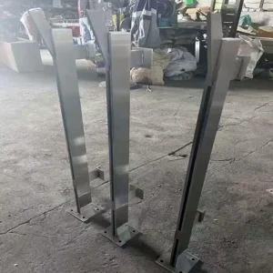
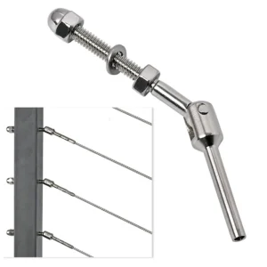
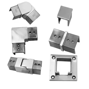
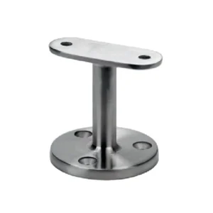
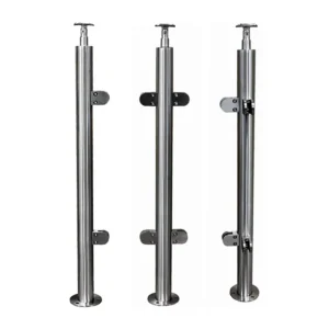
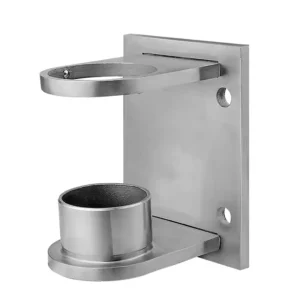
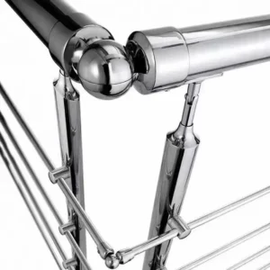
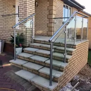
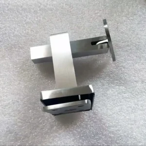
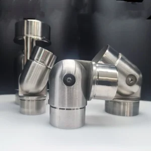
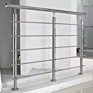
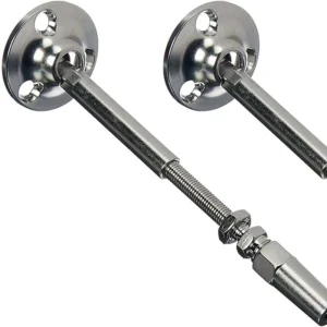
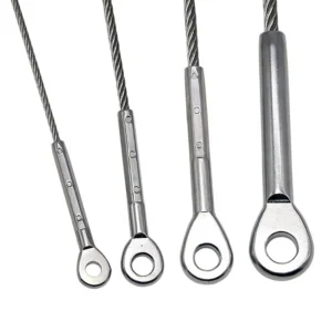
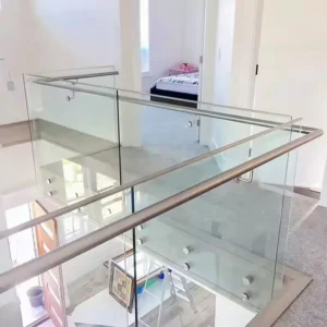
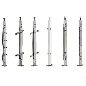
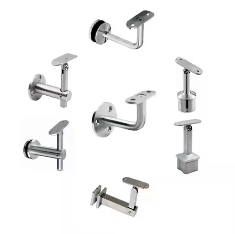
The public product image shows several visible bracket forms with different joints; it does not establish one common range or locking method. Give the required design angle, the expected site tolerance around that angle, and whether the setting will be made at the factory or on site. The proposed configuration should state its permitted setting range and any positions that are excluded.
Using only the extreme end of a slot or pivot may reduce contact, fastener engagement or clearance. The drawing should show the final locked position, not just the bracket in an unrestrained catalogue pose. If the railing geometry changes along a run, identify the bracket setting at each location rather than ordering one undifferentiated “adjustable” item.
Lock the setting and restrain rotation
An adjustable joint must become a defined connection after alignment. Ask the offer to identify the locking fastener, bearing faces, serration or locating feature, required access for tightening, and whether any secondary retention is part of the proposed supply. Appearance alone cannot prove that a pivot resists slip or that a set screw provides the system’s final capacity.
The anti-rotation strategy also depends on the post section. A square post can provide flat reference faces, while a round post may require a shaped saddle, multiple fixing points or another positive feature. For a hollow post, state wall thickness and internal access so the connection does not rely on unsupported local clamping.
Match both ends of the bracket
On the post side, provide the outside diameter or width, wall thickness, corner radius where relevant, connection location and any prepared holes, inserts or weld bosses. On the rail side, provide the handrail or top-rail section, centreline, slope, hole pattern and desired contact form. A flat support plate, curved saddle and clamp head are not interchangeable interfaces.
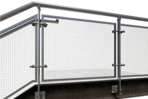
If the item is intended for a barrier rail rather than a graspable handrail, say so and include the adjacent post, rail and infill arrangement. A small bracket is one component of the railing system; its photograph or material description does not establish the performance or code compliance of the complete assembly.
Choose where adjustment happens
| Route | Useful when | What must be frozen |
|---|---|---|
| Factory-set bracket | Surveyed geometry is reliable and repeatability matters | Angle, hand, post location, rail contact and locking state |
| Field-set bracket | A bounded installation tolerance must be absorbed | Range, setting procedure, tightening access and inspection |
| Fixed bracket at measured angle | Movement is unnecessary and a simpler load path is preferred | Final geometry and installation tolerance |
Factory and site work must be explicit
The quotation should identify whether the bracket is supplied loose, assembled, preset, or matched to a prepared post. It should list included pins, screws, nuts, inserts and saddles, plus the proposed material/finish only where offered. The site scope should separately cover layout, drilling or welding, setting, final tightening, protection of finished surfaces and inspection of the complete railing connection.
Send these details for a usable proposal
Start with the post and rail sections, the nominal angle or offset, a photo or sketch of the location, approximate quantity and exposure condition. Before release, confirm the adjustment axis, minimum/maximum required setting, final locked position, post wall/bearing support, rail contact form, fasteners, anti-rotation method, handedness, factory/site work split and any project-specific testing or approval requirement. The proposal should list these items so a limited-adjustment bracket is not compared with a different mechanism under the same generic name.