Can a surface-mounted base plate safely replace a post that was originally embedded in a concrete core, or does the change in mounting method introduce conditions the original design never had to address? The answer depends on what remains in the slab after the old core is removed, how the new load path compares with the old one, and whether the surrounding concrete can accept new fasteners in the location the retrofit requires. None of that is visible until the existing condition is surveyed and compared against the proposed replacement.
Existing conditions that decide whether a surface-base retrofit is feasible
A core-mounted post transfers load into the slab through an embedded connection, where the concrete around the post shares in resisting lateral and overturning forces along the full depth of the core. A surface-mounted base plate transfers the same categories of load — lateral push, overturning moment, and uplift — through a shallower connection acting at the slab surface, carried by anchors and bearing contact rather than an embedded shaft. Converting from one method to the other is not simply a matter of fitting a new base over the old opening; it changes how forces reach the reinforcement and how much sound concrete must surround each new anchor point.
This means feasibility is not a property of the base plate itself but of the slab condition at the specific location the plate will occupy. Where the old core left the surrounding concrete intact, with no cracking radiating outward and no deterioration from prior water intrusion, a surface base has a reasonable chance of finding adequate bearing and anchor embedment nearby. Where the old core area has cracked, spalled, or been patched previously, the same slab may no longer offer a reliable load path at that exact spot, even if the visible surface looks serviceable after patching.
The slab’s internal condition — reinforcement layout, thickness at the specific point of interest, and any prior repair history — determines whether a surface base can be anchored at or near the original post location, or whether the plate location must shift to reach sound material. This is why a retrofit cannot be designed from the old post’s footprint alone. The original embedded post’s centerline tells the reader where the rail used to be, not where the new anchors can safely go. Confirming the existing condition at the proposed location, rather than assuming the old embedded-post area is automatically reusable, is the starting point every other decision in a surface-base conversion depends on.
New plate location versus old cores, cracks, edges, and reinforcement constraints
| Existing condition | Site evidence to verify | Location decision affected |
|---|---|---|
| Existing core | Position and condition of the removed post core | Placement of the proposed surface plate |
| Surrounding cracks | Crack locations around the existing core and proposed plate area | Whether the proposed plate layout can advance to project engineering review as drawn |
| Edge geometry and edge distance | Slab-edge geometry and the proposed plate’s distance from the edge | Feasibility of the proposed plate location |
| Slab thickness | Verified thickness at the proposed plate location | Engineering review of the proposed base and anchorage |
| Reinforcement constraints | Known constraints at the proposed new-hole locations | Hole layout submitted for review before drilling |
| Prior repairs | Location and condition of prior repairs within the proposed plate area | Whether repaired areas must be included in the verified existing condition |
Once the general feasibility question is framed, the project needs a location-specific check: does the condition at the exact spot where the new plate will sit support the anchors the base plate design calls for? The old core is the first reference point, because its position marks where the slab has already been disturbed and where any undocumented reinforcement cuts or voids are most likely to exist. A proposed plate that overlaps the old core, or sits immediately adjacent to it, inherits whatever uncertainty remains in that disturbed zone unless the condition there has been directly verified.
Cracking around the existing core changes the calculation in a different way. A crack that terminates before reaching the proposed plate area is a different condition from one that passes through the anchor pattern itself, because a crack intersecting an anchor location can reduce the concrete’s ability to develop the anchor’s intended capacity. This is a site condition that drawings alone cannot settle; it has to be confirmed against the actual proposed layout, not just the general vicinity.
Edge distance works on the same logic from a different direction. A slab edge that is close to the proposed plate reduces the concrete available to resist anchor pull-out or breakout on that side, so a plate location that would be acceptable mid-slab may not be acceptable near a perimeter or an expansion joint. Slab thickness at the proposed point interacts with both of these conditions, since a thinner section limits how deep an anchor can be set regardless of how clean the surrounding concrete appears. Reinforcement constraints add a further layer: if rebar position near the proposed holes is unknown or conflicts with the anchor pattern, the hole layout itself may need to shift before drilling can proceed. Prior repairs deserve the same scrutiny as original concrete, since a patch is only as reliable as the bond and condition underneath it, which is not always evident from the surface.
Revised post centerline, rail geometry, clearance, and finished alignment
| Geometry check | Comparison to make | Decision protected |
|---|---|---|
| New post centerline | Compare the proposed centerline with the removed embedded post centerline | Keep the retrofit from shifting rail alignment |
| Finished retrofit geometry | Compare the proposed finished geometry with the removed-post arrangement | Check whether the retrofit shifts usable clearance |
Even where the slab condition allows a new plate to be anchored safely, the retrofit still has to answer a separate question: does the resulting post position preserve the rail system’s intended geometry? A surface base plate occupies space differently than an embedded post, and the anchor pattern that satisfies the slab condition may not align with the original post centerline. If the new centerline shifts, every rail segment connecting to that post shifts with it, which can change alignment with adjacent posts that were not part of the retrofit.
Clearance is a related but distinct concern. The finished dimension from the base plate’s top surface to the rail, combined with any change in post stand-off from the slab edge, can alter the usable clearance behind or beside the railing line. A post that moves even a small amount toward or away from an edge changes that clearance, which matters where the railing adjoins a walking surface, a door swing, or other fixed clearance requirement already established by the original design.
Where the slab condition permits only a shifted plate location, the retrofit forces a choice: accept a shift in centerline and recheck how it affects rail alignment and clearance, or treat the shift as unacceptable and continue investigating until a location preserving the original geometry is confirmed. This is a condition-driven decision, not a default outcome — a shift that is acceptable in one project’s layout may compromise a clearance requirement in another. Comparing the proposed finished geometry against the removed post’s arrangement, rather than assuming that any plate fitted near the old location reproduces the same result, is what prevents the retrofit from silently altering the rail system’s functional dimensions. This comparison is covered in more detail in discussions of balcony railing post mounting details for new construction and retrofit projects, where the same centerline and clearance relationship recurs across different mounting conditions.
Load-path and anchorage inputs for project engineering review
| Review input | Include in the review package | Beslissingsgrens |
|---|---|---|
| Verified existing condition | Existing core, surrounding cracks, edge distances, slab thickness, reinforcement constraints, and prior repairs | Use the verified site condition rather than assuming the original embedded-post area is suitable for a surface base |
| Proposed plate layout | Plate location and planned new holes in relation to the surveyed conditions | Complete project engineering review before drilling |
| Revised post geometry | New post centerline, rail alignment, usable clearance, and finished geometry compared with the removed embedded post | Confirm the project-specific geometry before ordering replacement bases |
| Connection-interface condition | Patched core, waterproofing, drainage, and surface flatness at the proposed base | Treat these items as part of the connection interface rather than cosmetic closeout |
| Revised load path | The proposed load path for the surface-base conversion | Anchorage conclusions require project engineering review |
A surface-mount conversion changes the load path from the one the original design assumed, which means the anchorage cannot be verified by inspection alone. The buyer’s role at this stage is to assemble what has already been confirmed — the verified slab condition, the proposed plate layout, the revised post geometry, and the connection-interface condition — into a package that project engineering can evaluate as a connected system rather than as separate observations.
The reason these inputs need to travel together is that each one changes the interpretation of the others. A slab condition that would support one anchor pattern might not support a pattern shifted to preserve the original centerline, so the geometry decision and the anchorage decision are not independent. Similarly, a connection-interface condition — meaning how the base plate will bear on the surface, how it will be sealed, and how water will be kept out of the new anchor holes — affects the long-term performance of the same anchors that carry the structural load, so it belongs in the same review rather than being addressed afterward as a finishing step.
This is also the point where project information supplied by the customer enters a supplier’s configuration and quotation review: a basisplaat voor opbouwmontage selected to match the verified slab condition and the confirmed post geometry is a different specification than one selected from the plate’s appearance or nominal size alone, and the supplier can only match a plate to the project once the condition, layout, and geometry are documented together. Without that documentation, any proposed base is a guess at compatibility rather than a confirmed fit.
Anchorage conclusions — the specific anchor type, embedment, and spacing that the revised load path requires — are not something the existing condition survey or the geometry comparison can settle on their own. They depend on engineering judgment applied to the assembled inputs, informed by the kind of design and performance criteria addressed in documents such as ASTM E985, which covers permanent metal railing systems and rails for buildings at a general scope, and anchorage testing references such as ASTM E894, both of which require their full text to apply specific values or conclusions to a given installation. A specification structure such as Bovenste Fossa, 52 graden 00 minuten illustrates how a project might organize railing submittals, without establishing a universal requirement for this or any other retrofit.
Patching, waterproofing, drainage, and surface-flatness coordination
Where a core is removed and a surface plate takes its place, the slab around and beneath the new connection needs to perform several functions at once, and treating any one of them as a closeout item separate from the structural connection creates a gap in the work. The patched core is not just a cosmetic fill; it is part of what the new base plate will bear on or anchor near, so the patch material and its bond to the surrounding slab affect how reliably the connection interface performs over time.
Waterproofing at this location matters for a mechanism distinct from the structural one: water reaching the anchor holes or the patched core from above can migrate into the slab and affect the reinforcement or the bond between patch and original concrete, independent of whether the anchors were sized correctly. A surface base plate, because it sits on top of the slab rather than passing through it, changes how water moving across that surface is intercepted or redirected compared with the drainage path that existed around the original embedded post. If drainage was designed around the old post’s position and profile, a relocated plate can change how water collects or sheds nearby, which is a condition worth checking rather than assuming unchanged.
Surface flatness at the plate’s bearing area affects how evenly the plate’s load transfers into the slab. A plate resting unevenly on a patched or uneven surface concentrates load at high points rather than distributing it across the full bearing area the design assumed, which changes the effective anchorage condition even if the anchors themselves were specified correctly. These items — patching, waterproofing, drainage, and flatness — are properties of the same connection interface the anchorage review depends on, not separate finishing tasks to be resolved after the structural decision is made. Questions about base plate, anchor, and drainage coordination on concrete slabs recur across surface-mount installations generally, which is why they belong in the same review as the anchorage inputs rather than a later punch-list.
Approval point before drilling holes or ordering replacement bases
The sequence this retrofit follows has one clear gate: the verified existing condition and the proposed plate layout move forward for project engineering review before any new hole is drilled and before any replacement base is ordered. Drilling first and confirming the condition afterward reverses a dependency that cannot be reversed safely, because a hole placed before the crack pattern, edge distance, and reinforcement condition are confirmed may land in a location the engineering review would have rejected.
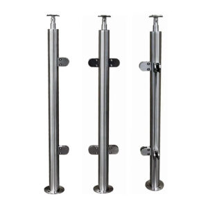
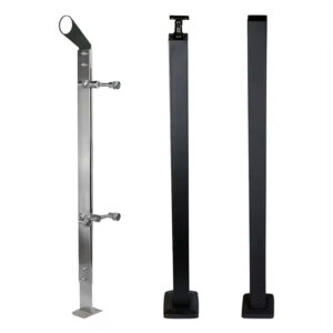
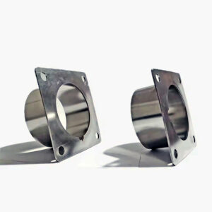
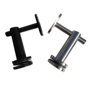
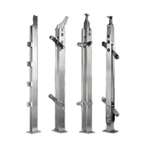
Ordering a replacement base ahead of that review carries a related risk from a different direction. A base plate ordered to match the original post’s nominal dimensions, without confirming the revised centerline and clearance the retrofit actually requires, may not fit the geometry that the slab condition and engineering review ultimately approve. This connects directly to the supplier side of the retrofit: once the project team has a reviewed plate layout and confirmed post geometry, that information becomes the basis for selecting the surface mount base plate and, where the original mounting method remains relevant to the comparison, the basissysteem voor de bevestiging van de kern it replaces — matched to the project’s confirmed dimensions rather than to a general product listing.
Where the review confirms that the slab condition at the proposed location fully supports the intended anchor pattern without compromise to centerline or clearance, the project can proceed to drilling and ordering on that basis. Where the review instead finds that achieving the required anchorage means accepting a shifted centerline, a different plate size, or additional patch work beyond what was first assumed, the drilling and ordering step waits until that revised layout has itself been confirmed. The approval point exists precisely to catch the difference between these two outcomes before either becomes physically irreversible.
Veelgestelde vragen
V: Can the new surface base simply cover the patched opening left by the embedded post?
A: Do not assume the patched opening is a suitable support area. Record the patch condition, surface flatness, waterproofing, and drainage at the proposed base, then include them with the plate layout in project engineering review.
V: What information should be collected before choosing a replacement base?
A: Collect the old core location, surrounding cracks, slab-edge geometry and proposed edge distance, slab thickness, reinforcement constraints, prior repairs, and the planned plate and hole locations. Also compare the proposed post centerline and finished rail geometry with the removed-post arrangement before ordering.
V: If the replacement post lines up with the old rail, is the retrofit ready to drill?
A: No. Matching the visible alignment addresses only part of the decision; the proposed plate location, connection interface, anchorage inputs, and revised load path still need project engineering review before drilling.
V: What should happen if a planned hole is close to a crack, slab edge, repair, or reinforcement constraint?
A: Stop at the layout stage and show the conflict in the verified site condition. The plate and hole arrangement should advance only after project engineering review of that project-specific condition.
V: How can the retrofit avoid reducing usable clearance?
A: Compare the proposed post centerline and complete finished geometry with the removed embedded-post arrangement. Resolve any shift in rail alignment or usable clearance in the reviewed layout before replacement bases are ordered.