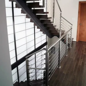
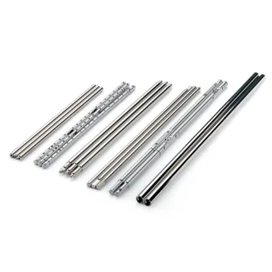
Swageless cable tensioners combine field-assembled cable termination with an adjustment mechanism, without using a traditional swaging press to form that termination. They are useful when cable length will be finalized on site, but they are not automatically tool-free, reusable or compatible with every cable. Start with the exact cable diameter and construction, the two end connections, the post interface and the available installation tools; a photo or sketch and estimated quantity are sufficient for an initial inquiry.
Ask ESANG about a swageless tensioner match
Swageless describes the termination method
A swageless fitting mechanically grips a prepared cable end using a design-specific arrangement such as jaws, a wedge, a cone or an insert. The exact mechanism and sequence vary. A buyer should therefore compare the cable compatibility, component set, cut preparation, assembly steps, inspection method and required tools—not simply the word “swageless.”
Swaged terminals use a matched press or hand swager to permanently compress a terminal onto the cable, either in a factory or on site. Swageless installation avoids that traditional operation, but still commonly needs a cable cutter and wrenches, hex keys or a dedicated release/assembly tool. Clean cable cutting matters because crushed or splayed strands can prevent correct insertion.
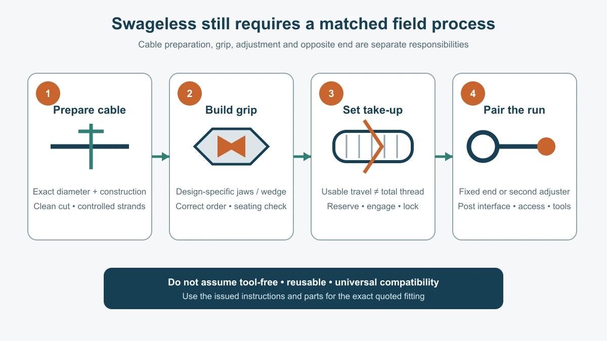
Match diameter and construction as one field
A cable marked only by nominal diameter is not a complete compatibility input. A semi-flexible 1×19 strand and a more flexible 7×7 cable can behave differently when cut and can require different gripping components. Some market fittings accept multiple constructions; others are restricted to one construction or use a different internal part for each. Those supplier examples are not evidence that an ESANG proposal is universal.
The proposed fitting should name the accepted cable diameter, construction and material requirement. It should also state whether the cable is included, supplied in bulk, cut on site or supplied as a finished assembly. If the cable is sourced separately, the proposal should identify who confirms the compatibility and what end preparation is required.
Build the fixed/tensioning pair
A swageless tensioner provides both a mechanical cable grip and take-up at one end of a run. The opposite end still needs a compatible fixed termination or another tensioning end. Fixed options may use a mechanical terminal, eye, fork, ball, stop or surface-mounted fitting depending on the post. The pair must be recorded together so the cable length, connector geometry and installation sequence agree.
One tensioning end keeps the assembly simple when its travel covers field tolerance. Two adjustable ends can help center an assembly or compensate for difficult access, but each requires safe thread engagement and locking. A fixed end and tensioning end from different product families should not be mixed on appearance alone.
Adjustment travel is independent of the cable grip
The gripping mechanism holds the cable; the threaded or turnbuckle mechanism changes the effective length. Confirm closed length, open length, usable take-up, thread designation, minimum engagement, starting position and the method used to lock the final setting. The installer should not consume all travel merely to overcome an inaccurate cable cut.
Leave controlled installation reserve based on the actual run and product instructions. A tensioner assembled fully closed has no further closing travel; one opened past its permitted engagement is not made acceptable by a locknut. The wrench flats, body and lock also need a clear tool path after the cable is in place.
Through-post and surface-mounted versions change site work
| Montageroute | Useful condition | Benodigde informatie |
|---|---|---|
| Via de paal | Threaded adjustment or end cap is reached from the rear of a terminal post | Post depth, wall thickness, hole and bearing detail, rear clearance and thread projection |
| Opbouwmontage | Termination stays on an accessible inside face | Mounting plate or fork, fasteners, edge distance, pin geometry and line of pull |
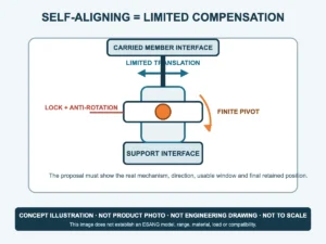
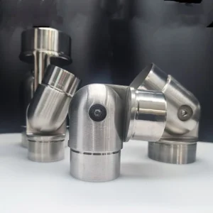
| Pivoting angle end | Stair or sloped run meets the post at a non-perpendicular angle | Actual angle, pivot plane, articulation limit and interference envelope |
A hollow post may need an internal detail or local reinforcement defined by the railing designer. A surface fastener set must match the post or substrate. The tensioner does not establish the capacity of the post, anchor or complete guard. If the primary challenge is a stair or ramp angle, compare multi-angle cable tensioners rather than assuming the swageless grip can articulate.
A safe field plan is product-specific
A general sequence is to confirm the run and end pair, cut the cable with a suitable cable cutter, keep the strand end organized, install the design-specific gripping parts in the stated order, verify seating, connect both ends, take up the cable and lock the adjustment. This is not an installation instruction for an unselected product. The issued instructions for the exact quoted design must define insertion, tightening, inspection and any rework limits.
Do not assume the termination can be opened and reused. Some fittings use a replaceable gripping element, some have a dedicated release method and some require new parts or a new cable end after disassembly. If future removal matters, request a written reuse policy and the replacement parts list with the quotation.
Separate component, assembly and system scope
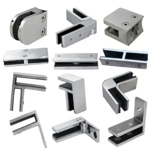
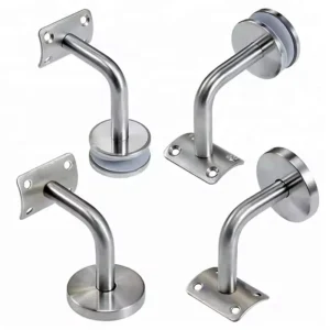
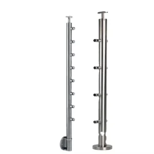
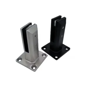
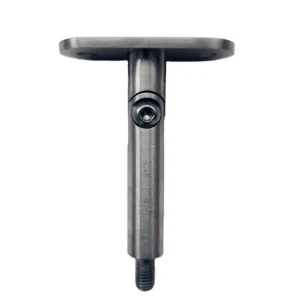
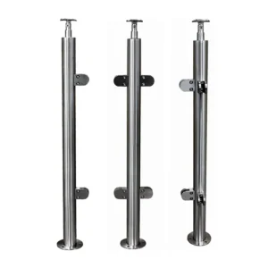
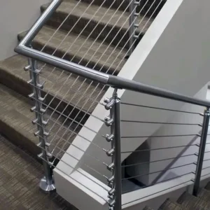
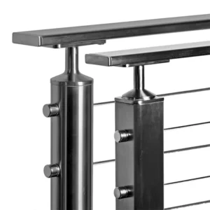
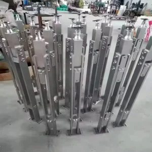
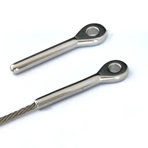
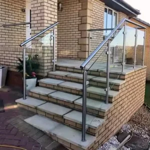
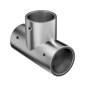
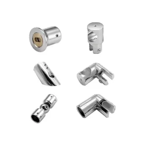
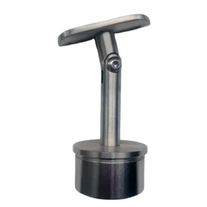
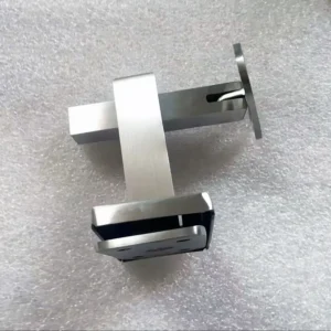
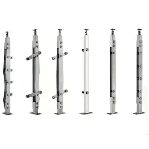
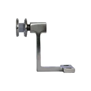
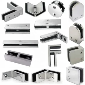
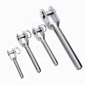
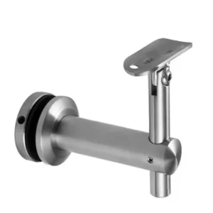
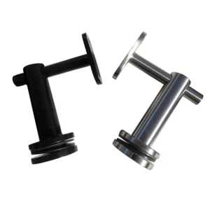
The photographed hardware on this page shows through-post cable components and hand tools, but the image does not verify their internal gripping mechanism, material, cable compatibility or performance. The formal proposal must identify what the actual product contains. A supply may cover a tensioner body, its internal gripping pieces, a matched fixed end, bulk cable, cut cable assemblies, mounting hardware or dedicated tools; none should be assumed from the page title.
Post drilling, reinforcement, anchors, railing design, installation, final tension, code review and system acceptance remain outside a component quote unless expressly included. A “heavy duty” option, if requested, must be linked to an exact size, end configuration, working-load basis and supporting documentation. Swageless construction is not itself a load grade.
Mismatch consequences to prevent
- Correct diameter, wrong cable construction: the cable may not seat or may be gripped in a way the fitting was not designed to accept.
- Frayed or crushed cut: strands can obstruct insertion and make visual inspection unreliable.
- Missing or reversed internal part: the termination can appear assembled without achieving the intended grip.
- Too little take-up after field cutting: the cable cannot reach the required final setting.
- No access behind the post: a through-post version cannot be assembled or re-tensioned.
- Reuse assumed without instructions: worn gripping parts or a previously marked cable end may be placed back into service incorrectly.
Inquiry fields that close the compatibility gaps
Send cable diameter, construction and source if known; run lengths and quantities; cable direction and stair conditions; fixed and tensioning end preference; post material, profile, wall thickness and hole layout; through-post or surface-mounted interface; rear and side access; desired take-up and installation reserve; thread and locking preference; available cable cutter and assembly tools; whether reuse is required; material and finish requirement; exposure; and whether cable, fixed ends, mounting parts and tools are to be included.
The proposed configuration should return the exact cable compatibility, gripping parts, end pair, closed/open length, usable take-up, thread and locking details, mounting interfaces, assembly and inspection tools, replacement or reuse policy, itemized supply boundary and any configuration-specific load documentation. That prevents “swageless” from hiding the details that determine whether the field assembly will work.