A railing anchor can carry the load it was designed for and still fail the project if the slab underneath it cannot deliver that capacity at the chosen location. Edge distance and slab thickness are not finishing details checked after layout; they determine whether the anchor layout drawn in the shop can actually be drilled where the drawing shows it. The question a buyer or fabricator has to answer before fabrication proceeds is whether the surveyed slab matches the assumptions the layout was built on.
Why slab geometry constrains an anchor layout
An anchor only performs as intended when the surrounding concrete can transfer load into the anchor without breaking out, splitting, or losing confinement. Edge distance exists because concrete near a free edge has less material resisting a cone of breakout than concrete surrounded on all sides; where an anchor sits close to an edge, the available breakout surface shrinks and the connection’s effective capacity changes even though the anchor itself has not changed. Slab thickness works the same way from a different direction: it governs how much embedment depth is actually available once cover, reinforcement, and any under-slab conditions are accounted for, and it limits how much confinement exists beneath the anchor.
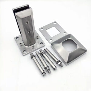
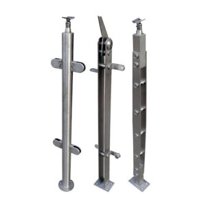
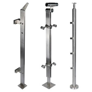
These two dimensions interact with the base-plate footprint and anchor layout rather than standing apart from them. A base plate sized for a given post and load carries a hole pattern that assumes each anchor sits at or beyond a minimum distance from any free edge and within a slab thick enough to develop the anchor’s embedment. If the slab in the field has a different edge location than the drawing assumed, or is thinner than the design assumed, the base plate and anchor positions reviewed on paper no longer describe the condition that will exist at the drilling location. The layout is not wrong in the abstract; it is wrong for that slab.
This is why slab geometry has to be treated as a constraint on the layout rather than a background condition confirmed once and forgotten. Where a project moves from one mounting location to another along the same railing run, or where the same base-plate design is reused across multiple posts, each location can present a different edge distance, a different thickness, or a different proximity to reinforcement or an opening. A layout accepted at one post position does not transfer automatically to the next; the geometry has to be checked at each location the anchors will actually occupy. Surface-mount base plates depend on this location-by-location verification because the plate’s anchor pattern is fixed once fabricated, so any mismatch between the fabricated pattern and the as-built slab becomes a field problem rather than a drawing revision.
Edge, thickness, reinforcement, and opening data to collect
| Site condition to capture | Compare with | Decision affected |
|---|---|---|
| Surveyed slab edge location and anchor edge distance | Actual base-plate footprint and anchor layout | Whether the planned hole pattern must change before fabrication or drilling |
| Slab thickness | Embedment demand for the selected anchor and project loads | Whether the anchor selection or plate layout requires project-specific revision |
| Reinforcement location | Each planned anchor position | Whether a hole must move; moving it changes the reviewed load path and triggers layout coordination |
| Nearby openings | Actual base-plate footprint and anchor layout | Whether the anchor layout or mounting detail must be revised |
Before a base-plate and anchor layout can be treated as reliable, the project needs site data that describes the slab as it actually exists, not as it was assumed during design. Four categories of information matter because each one can independently invalidate a layout that looks correct on paper: the surveyed edge location relative to each anchor position, the actual slab thickness, the location of reinforcement relative to planned anchor positions, and the presence of openings near the planned footprint.
Edge location matters because drawings are typically produced from a nominal slab dimension, while the as-built edge can vary from that nominal line. An anchor positioned to meet a minimum edge distance against the nominal edge may fail to meet it against the actual edge if the slab was poured narrower, wider, or at a different alignment than planned. Slab thickness carries a parallel risk: a design that assumed a given thickness to support a given embedment depth cannot be assumed to hold if the as-built slab is thinner, because the embedment that the anchor needs may no longer be available without reaching into conditions the design never accounted for.
Reinforcement location adds a different kind of constraint. An anchor layout drawn without a steel survey assumes clear concrete at each hole position; where reinforcing steel actually occupies that position, the installer faces a choice between drilling through steel, which is not an acceptable resolution on its own, or shifting the hole. Any such shift changes the anchor’s position relative to the edge and relative to the other anchors in the pattern, which is why it cannot be treated as a minor field adjustment.
Nearby openings, whether drains, conduit penetrations, or other slab penetrations, reduce the effective concrete available around an anchor in much the same way a free edge does, and an opening close to a planned anchor position can behave like an additional edge that the original layout did not account for.
Collecting this data before fabrication, rather than during installation, gives the project team the chance to revise the plate or mounting detail on paper instead of in the field. Where the data is gathered only after the base plate is already fabricated, any conflict it reveals becomes a schedule and coordination problem rather than a drawing change.
Base-plate reactions and anchor demands for project review
A base plate transmits the railing’s loads into the anchors as a set of reactions, and those reactions are what the anchor layout and embedment actually have to satisfy. The plate geometry, the post height, and the direction and magnitude of the applied load together determine how much tension, shear, and in some configurations prying action each anchor in the pattern must resist. Because these reactions depend on the specific plate and post configuration, a generic statement about an anchor’s rated capacity does not describe what that anchor will experience once it is installed under a particular base plate carrying a particular railing.
This is the gap that project-specific review is meant to close. A catalogue capacity for an anchor describes performance under defined test or reference conditions; it does not describe performance once that anchor is embedded in a specific slab, at a specific edge distance, carrying a specific base plate’s reactions. The anchor, the substrate condition revealed by the site survey, and the loads the railing imposes have to be reviewed together before the connection can be considered resolved. Where any one of those three changes, the review has to be revisited, because the reactions at each anchor depend on the full combination rather than on the anchor’s rating in isolation.
ASTM E894 identifies anchor tension and shear, post-base testing, and mounting verification as the subjects relevant to anchorage review, which frames the kind of information a project-specific review needs to produce, though the metadata available does not supply the edge-distance or slab-thickness values themselves; those remain dependent on the project’s own design and testing. ASTM E985 covers permanent building railings and sets out basic design and load and deflection criteria for the railing itself, but the field conditions and anchorage dimensions that connect that railing to a particular slab stay outside that document’s scope and fall to the designer and the governing code authority to resolve for the project at hand.
For the buyer, this means the review is not a one-time check against a published number. It is a comparison between what the base plate will demand at each anchor and what the as-built slab, at that anchor’s actual location, can deliver. Anchoring systems selected for a project have to be evaluated against that comparison rather than against a capacity figure read off a data sheet.
Field conflicts that force layout or mounting changes
Even a layout that was reviewed and approved on paper can meet a conflict once the crew is on site with a drill. The conflicts that matter are the ones that change the anchor’s relationship to the edge, the slab thickness, the reinforcement, or a nearby opening, because any of those changes the load path the original review was based on.
The clearest example is reinforcing steel encountered at a planned hole location. Where this happens, moving the hole is the obvious field response, but moving it is not a neutral fix. The new position has a different edge distance, sits over a different thickness condition if the slab is not uniform, and may bring the anchor closer to another anchor in the same pattern or to an opening that was previously clear. Each of these changes the reactions and capacities the original layout was reviewed against, which is why a relocated hole has to trigger layout coordination rather than being treated as a installer-level adjustment resolved without revisiting the design.
A similar conflict arises where the surveyed edge location differs from the drawing, or where the slab is thinner at the installation point than the design assumed. In either case, the base plate as fabricated may no longer be able to achieve the anchor positions the review approved. Where the edge is closer than assumed, the available options are to shift the entire plate footprint, to select a different anchor or embedment solution suited to the reduced edge distance, or to revise the connection detail entirely; which option applies depends on how much clearance remains and what the plate’s geometry allows. Where the slab is thinner than assumed, the available embedment may not support the original anchor choice, which can force a different anchor type or a different mounting approach rather than a simple hole relocation.
These conflicts are why field verification has value only if it happens before the plate is committed to a fixed hole pattern. A surface-mount base plate fabricated to one layout cannot absorb a field conflict the way a layout still in drawing form can; once fabricated, a conflict becomes a return trip to the fabrication stage rather than a markup on a drawing.
Approval evidence before drilling or fabrication proceeds
| Approval input | Wat het ondersteunt | Boundary to retain |
|---|---|---|
| Surveyed slab conditions, including edges, thickness, reinforcement, and nearby openings | Comparison of actual geometry with the base-plate footprint, anchor layout, and embedment demand | Survey data alone do not approve the connection |
| Coordinated base-plate and anchor layout after field conflicts are resolved | Alignment of planned hole positions with the reviewed layout and load path | Moving a hole to clear reinforcement triggers layout coordination |
| Project-specific review of the selected anchor, substrate condition, and project loads | Basis for reviewing the connection | Generic catalogue capacities do not approve the connection |
| ASTM E894 anchorage subject coverage | Identifies anchor tension and shear, post-base testing, and mounting verification as anchorage subjects | Does not provide project edge-distance or slab-thickness values |
| ASTM E985 railing criteria scope | Covers permanent building railings and basic design and load/deflection criteria | Field conditions and anchorage dimensions remain project-specific under the designer and code authority |
The decision to proceed with drilling or fabrication depends on assembling evidence that actually closes the gap between design assumptions and as-built conditions, rather than evidence that merely documents one side of that gap. Surveyed slab conditions, covering edge location, thickness, reinforcement, and nearby openings, establish what the slab can offer at each anchor position, but a survey on its own does not approve a connection; it only supplies the comparison data the review needs.
The second piece of evidence is a base-plate and anchor layout that has been coordinated against that survey and against any conflicts the survey or field drilling revealed. Where a hole has been moved to clear reinforcement, that coordination has to show the revised position was checked against edge distance, thickness, and the reactions the plate imposes, not just confirmed as clear of steel.
The third piece is the project-specific review of the selected anchor, the substrate condition, and the project loads together. This is the step that converts a catalogue-rated anchor into an approved connection for the specific slab and base plate in question; without it, the anchor’s published capacity describes a reference condition rather than the condition the project will actually impose.
Where ASTM E894 and ASTM E985 inform this process, they do so by identifying what subjects the review needs to address and what criteria the railing itself has to meet, not by supplying the edge-distance or slab-thickness figures for a given project; those figures remain the output of the project’s own design and field verification, subject to the designer and the governing code authority. A buyer assembling approval evidence should expect to present surveyed conditions, a coordinated layout, and a project-specific review of anchor and substrate together, since any one of these without the others leaves the connection unresolved. The project data a buyer supplies, including slab conditions and the intended base-plate and anchor configuration, is also what allows a supplier’s quotation or configuration review to address the actual installation rather than a generic assembly, which is a separate step from the structural approval itself but depends on the same site information being gathered and confirmed before fabrication proceeds.
Veelgestelde vragen
V: Can a railing base plate be fabricated before the slab conditions are surveyed?
A: Fabrication should follow confirmation of the actual slab edge, thickness, reinforcement locations, and nearby openings. Comparing those conditions with the base-plate footprint and planned anchors early allows the mounting detail to be revised before holes are fixed in the plate or drilled on site.
V: What should happen if a planned anchor hole conflicts with reinforcing steel?
A: Treat the conflict as a layout change rather than simply moving the hole in the field. The revised hole position, base-plate layout, and resulting load path should be coordinated and reviewed before drilling proceeds.
V: Are catalogue anchor capacities enough to approve the railing connection?
A: No. Approval requires project-specific review of the selected anchor, actual substrate condition, connection geometry, and project loads; a published capacity alone does not confirm that the planned layout is suitable for the slab.
V: Do ASTM E894 or ASTM E985 provide the required edge distance and slab thickness for a project?
A: Not by themselves. ASTM E894 identifies anchorage subjects such as tension, shear, post-base testing, and mounting verification, while ASTM E985 addresses permanent railing criteria; the actual anchorage dimensions still require project-specific determination by the designer and code authority.
V: What information should the drilling team receive before work starts?
A: They should receive the coordinated base-plate and anchor layout matched to the surveyed slab conditions and the reviewed connection. If the site edge, thickness, reinforcement, openings, or hole positions differ from that layout, the discrepancy should trigger coordination before any hole is moved or drilled.