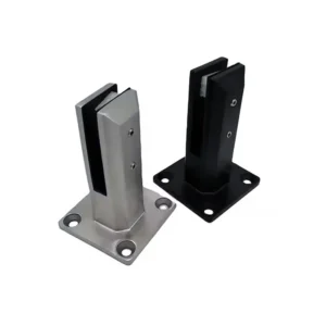
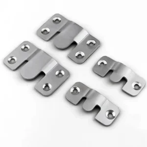
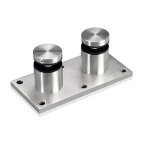
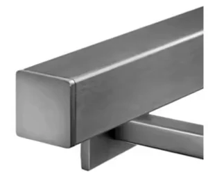
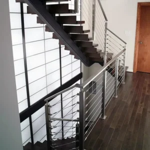
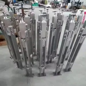
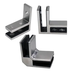
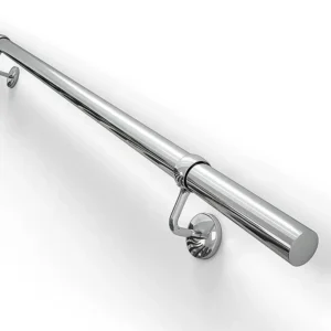
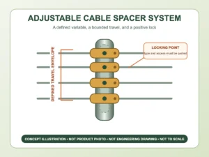
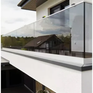
Use mini glass clamps when the connection envelope is genuinely constrained—not as a shortcut for the mechanical specification. Send the panel arrangement, available clearance, glass build-up and support detail so the compact form can be checked against the required connection.
Discuss mini glass clamps on WhatsApp
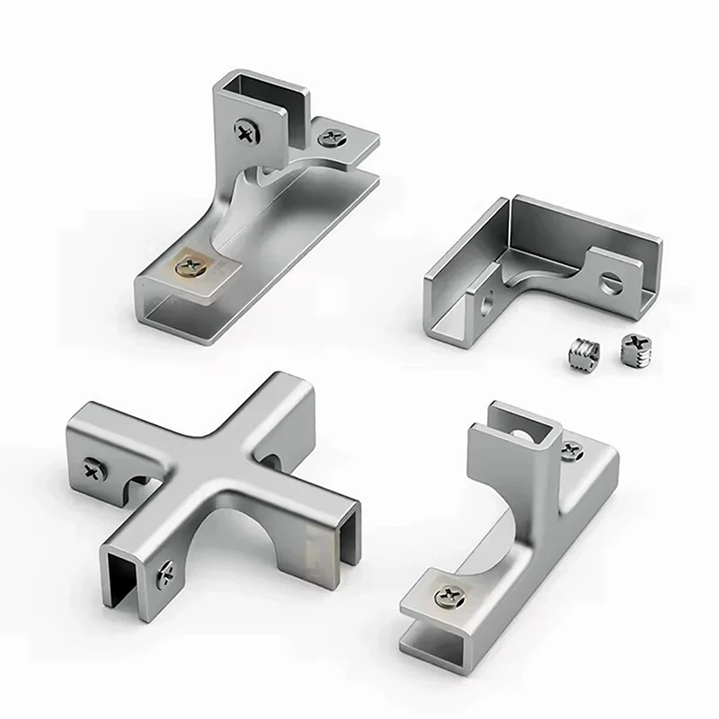
Mini describes the envelope, not the duty
A smaller visible body may help where sight lines, furniture, trim, a return panel or tool access limit the available space. It does not establish a lighter or heavier load rating, a fixed glass thickness or universal compatibility. Start by recording the maximum permitted projection, face width, height and installation-tool clearance at each location.
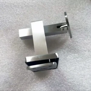
Also define the connection route. A compact clamp may be intended for panel-to-panel alignment, a corner return, a panel-to-flat support or another bounded detail. Similar-looking straight and corner pieces are not interchangeable, and a connector that aligns two panels should not be treated as the complete support for a guard without system approval.
Glass edge and hole planning becomes more sensitive
Provide the glass construction, nominal build-up and tolerance, edge finish, interlayer where relevant and project-required heat treatment. A compact body leaves less room to absorb a wrong hole position, unexpected edge detail or thick replacement inlay. Confirm the glass drawing before fabrication.
The proposed configuration should state:
- whether the glass is drilled, notched or clamped without holes;
- the approved hole position and edge distance when drilling is required;
- the inlay or gasket for the stated glass build-up;
- the locating, anti-slip or other retention method;
- the permitted panel gap and connector orientation.
For laminated glass, ask the responsible system designer to define how panel slip and post-breakage behaviour are addressed. The label “mini” and the presence of a dark inlay do not answer those questions.
Check the back, mounting face and fastener access
For panel-to-support use, issue the support type and dimensions: flat plate, wall, square profile, round tube or project-specific adapter. Include thickness, rear access and nearby obstructions. A compact clamp can still require a mounting screw, stud, backing plate or anchor path that is larger than the visible face.
Separate the glass-contact screws from the support fastener and from any locating pin. The offer should show which fasteners are included, how they are accessed, and which building anchors remain outside the component supply. Concealing a screw may improve appearance but can make inspection or replacement harder; decide that trade-off before finalizing trim.
Choose finish and material for the actual exposure
State indoor/outdoor use, salt or de-icing exposure, pool or cleaning chemicals, and the desired appearance. If a particular stainless grade or finish is required, request it as a proposed configuration and ask the quote to identify the body and exposed fastener materials. Do not assume every compact shape is available in every material, colour or finish.
A darker coating, polished face or brushed surface is an appearance choice as well as a maintenance interface. Request a controlled finish description or sample where several hardware types must match.
Use the quote to close the compact package
| Selection | Input needed | Proposal should identify |
|---|---|---|
| Connection path | Straight, corner, return or support connection | Exact compact body and orientation |
| Envelope | Available face, projection and tool clearance | Installed dimensions and screw access |
| Glas | Build-up, tolerance, edge and holes/notches | Matched inlay and preparation drawing |
| Retention | System-required locating or anti-slip strategy | Included pin/device and its role |
| Montage | Support profile, thickness, backing and access | Seat, fastener and excluded anchorage |
Keep the complete system boundary visible
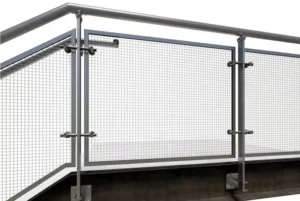
Panel dimensions and make-up, clamp or connector count and spacing, supports, rails, bases, anchors and substrate determine the complete assembly. A compact connector may align or hold a local edge without carrying every system action. The responsible project designer or system supplier must approve the full load path and applicable project requirements.
Information for a mini clamp inquiry
- a marked plan or elevation showing every clamp and connector location;
- the maximum visible envelope and nearby clearance restrictions;
- glass construction, nominal thickness/tolerance, edge finish and existing holes;
- panel gaps, straight/corner relationship and installation sequence;
- support profile and fastening access where one side is not glass;
- environment, finish, estimated quantity, destination and required documents.
A sketch and estimated quantity are enough to begin. Unknowns should remain marked until the proposed body, inlay, retention route and fasteners are frozen.
Mini glass clamp questions
Does mini mean suitable for thin glass?
No. Physical size and glass compatibility are separate. The exact glass build-up and matched inlay must be stated in the proposed configuration.
Can a compact connector be used as the only panel support?
Only when the complete engineered system assigns it that role. Do not infer system capacity from the connector shape or size.
Are straight and corner mini clamps interchangeable?
No. They impose different geometry and panel gaps. Mark each connection on the drawing and quote them as separate line items.
Can the clamp be supplied without an anchor?
Yes, for a component inquiry, but the quote must state which screws, inlays and locating parts are included and which support anchorage is excluded.