A custom wire mesh infill supplier can fabricate cleanly matched panels only if the drawing package tells them where each run sits, how each opening is sized, how the mesh meets its frame and the surrounding rail, and who owns each open decision. Missing any one of these forces the supplier to guess at design intent that belongs to the project team, not the shop. The question is not whether drawings are required, but which views and callouts let the supplier review scope without inventing it.
Start with Overall Plans and Elevations
A plan and elevation set exists to locate every railing run and show how one run differs from the next. Without this, a panel count or a single typical detail tells the supplier nothing about where a level run ends and a stair or ramp condition begins, or where a balcony returns into a corner. Each of these transitions changes what the mesh panel adjacent to it must do: a corner condition may require a non-repeating panel shape, a stair condition introduces a sloped top edge, and a transition between a balcony and a terrace may shift the baseline the panel height is measured from.
Where the project provides only a representative detail and a total quantity, the supplier is left to assume that every run is identical, which is rarely the actual design intent once terraces, returns, and stair flights enter the layout. A plan view resolves this by showing the physical path of each run in relation to adjacent construction, so the supplier can see where a run is interrupted by a column, a door opening, or a change in level. An elevation view resolves a different problem: it shows how panels are arranged along that run, including which heights the project has actually specified and where a repeated bay stops repeating.
A stair or ramp view carries information that a flat plan cannot show, because slope changes both the panel geometry and the way the mesh meets the top and bottom rail. Where a run rises with a stair, the infill panel is no longer a simple rectangle, and the supplier needs the slope condition shown rather than inferred from a note that says “sloped.” A key or reference plan then ties every detail and panel mark back to a physical location, which matters once the number of panel types grows past what a single elevation can carry clearly. Without that linkage, a detail sheet and a panel schedule can describe the same railing run in ways that do not visibly connect, and the supplier has no reliable way to confirm which detail governs which physical location.
| Drawing view | Information it should convey |
|---|---|
| Plan | Run locations, corners, transitions, and adjacent construction |
| Elevation | Panel arrangement, heights supplied by the project, and repeated conditions |
| Stair or ramp view | Slope, landings, and geometry changes |
| Key/reference plan | How details and panel marks connect to locations |
Define Each Panel Opening and Geometry
Once the overall run is located, each individual opening needs its own defined geometry, because a wire mesh panel is fabricated to the specific clear opening it fills, not to a general run dimension. An opening dimension depends on the posts or framing members that bound it, and that dimension changes wherever post spacing is not uniform along a run. A supplier working from a single typical width across an entire project risks producing panels that do not fit locations where the framing spacing was adjusted for a corner, a wider bay, or a field condition discovered after the typical detail was drawn.
Where a run includes a raked or sloped condition, the opening is no longer defined by height and width alone; it also depends on whether the top edge is meant to follow the slope or step to remain level, since these are two different design intents that produce two different panel shapes from the same footprint. The drawing needs to state which condition the project intends rather than leave the supplier to choose between them, because raked and stepped panels are not interchangeable once fabricated.
Handed conditions and corner relationships add a further layer of variation. A panel that sits at a corner or turns to match a mirrored condition elsewhere on the project is not a simple duplicate of a straight-run panel, even if the nominal dimensions match, because the edge treatment or frame relationship at the corner may differ from the edge treatment used mid-run. Where the project has non-repeating shapes, each one needs its own identity rather than being grouped with a nominally similar type.
This is why a panel schedule matters alongside the drawings themselves: it gives every unique opening a mark, ties that mark to a quantity, and lets the supplier confirm fabrication scope against a defined list rather than a general description of “typical” and “atypical” conditions. Gaas opvulpanelen reviewed against such a schedule can be checked one mark at a time, which reduces the chance that a variation buried in a single run gets fabricated as if it were a repeat of the standard type.
| Geometry item | Show on drawing or schedule |
|---|---|
| Panel identity | Unique mark and quantity |
| Opening or panel size | Project-defined width, height, and relevant datum |
| Run type | Level, raked, or transition condition |
| Variation | Handed condition, corner relationship, or non-repeating shape |
Detail Posts, Rails, Edges, and Fixings
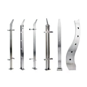
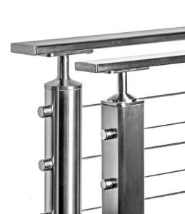
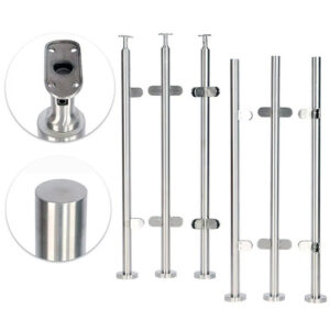
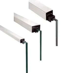
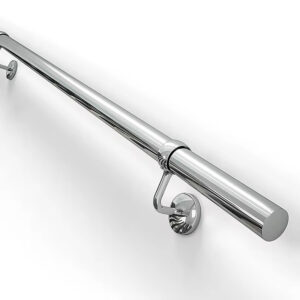
The panel opening only defines the space the mesh fills; the interface detailing defines how the panel actually connects to the structure around it, and this is where fabrication drawings diverge from contract drawings in both purpose and level of detail. Post shape and spacing govern the framing the panel must fit inside, and where post spacing varies along a run for structural or layout reasons, the fixing locations for each panel will vary with it. Top- and bottom-rail profiles matter because the mesh frame or edge condition has to relate physically to whatever profile the rail presents; a rail with a captured slot and a rail with a surface-mounted bracket call for different edge or frame concepts on the mesh panel itself.
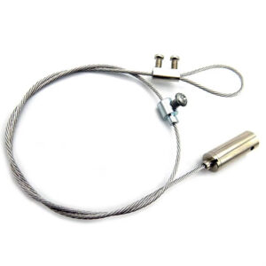
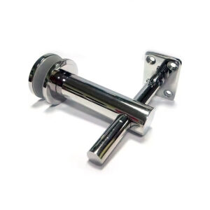
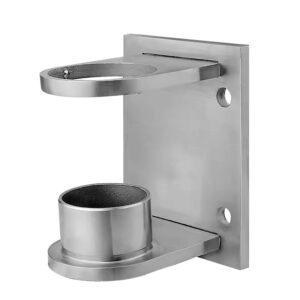
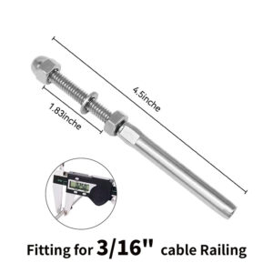
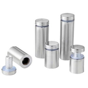
The mesh frame or edge treatment is a project-level decision, not a default the supplier can assume: whether the mesh terminates in a formed frame, a wrapped edge, or another edge concept changes both the visible appearance and the way the panel is fixed at its perimeter. Where the project intends specific fixings — tabs, clips, brackets, clamps, sleeves, or another connection type — their type and location need to be shown or specified rather than left as a general note, since these fixings determine how load transfers from the mesh panel into the surrounding rail and post assembly.
Bovenste Fossa, 52 graden 00 minuten, the federal metal railings guide specification, illustrates why fabrication drawings carry this level of member and connection detail rather than reproduce the contract drawings: fabrication drawings exist to show complete member and connection information, including anchorage, ahead of fabrication, which is a different purpose from the contract drawings’ role of establishing design intent. Referencing the top rails and bottom rails category alongside the mesh detail helps keep this interface visible, since the mesh panel’s edge condition and the rail’s profile have to be resolved together rather than reviewed as separate, unrelated components. Where a project’s rail profile is still undecided at the time mesh shop drawings are prepared, that open item needs to be flagged rather than assumed, because a mismatch between the assumed rail profile and the final one changes the mesh frame’s fixing points.
| Interface | Detail to provide |
|---|---|
| Berichten | Shape, spacing, and connection locations |
| Boven- en onderrails | Profiles and support relationship |
| Mesh edge/frame | Edge treatment, frame concept, and visible-joint intent |
| Bevestigingsmiddelen | Type and location of tabs, clips, brackets, clamps, sleeves, or specified alternatives |
Identify Materials, Finishes, and Visual Controls
Material and finish information belongs to the project specification, not to a default the supplier applies from a similar-looking prior panel. The drawing package should reference the specified material and finish directly rather than describe an appearance in general terms, because a described appearance (“brushed” or “matte”) can correspond to more than one achievable finish depending on the material and process behind it. Where a sample or an accepted appearance reference exists, the drawings should point to that reference rather than restate a verbal description of it, since a verbal description is open to interpretation in a way a physical or approved reference is not.
Visual control matters differently depending on where a panel sits within the overall composition. A panel in a highly visible location, at eye level or along a primary circulation path, carries different scrutiny of joint and edge appearance than a panel in a location seen briefly or from a distance. The drawings do not need to invent a tolerance or acceptance standard where none exists in the project specification; instead, they should flag which areas the project treats as requiring closer visual control, so the supplier knows where exposed joints, edge treatment, or finish consistency are a review criterion rather than a background condition.
This distinction between visual finish and structural or corrosion performance is separate: a finish decision governs appearance, while material grade governs long-term performance in the installed environment, and the two should not be assumed to travel together on a drawing that only specifies appearance. Where the project specification names a material grade or corrosion-performance requirement, that requirement needs to be stated on its own line rather than inferred from the finish description, since a finish note alone does not establish which grade of material sits beneath it.
Mark Design Inputs, Field Conditions, and Approval Ownership
The final piece of the drawing package is the information that establishes what the supplier is being asked to review, as distinct from what remains a decision for the project team. Project specifications and any structural or load criteria need to come from the party responsible for that engineering, because a supplier reviewing manufacturability is not the same as a supplier assuming responsibility for the complete installed assembly’s structural performance. Where load or code criteria exist for the project, they need to be stated as inputs on the drawing rather than left for the supplier to assume, since assumed criteria cannot be verified against what the responsible designer actually intended.
Field conditions carry a parallel but distinct role. Known dimensions taken from the actual structure, the type of supporting structure the railing attaches to, and any installation constraints discovered on site all affect whether a panel fabricated to drawing dimensions will actually fit once installed. Where field verification has not yet occurred at the time drawings are issued, that gap needs to be marked as an open item rather than treated as resolved, because a dimension assumed from a contract drawing can differ from the as-built condition it is meant to represent.
Deviations and open items deserve their own place in the package rather than being buried in general notes, since these are the specific points requiring a response before the supplier can release the drawings for fabrication. Leaving them unmarked does not remove the ambiguity; it only delays discovery of it until after fabrication has begun.
The approval path itself is part of what the drawings need to establish: which party coordinates the interfaces between trades, which party carries engineering and code responsibility, and which party issues the fabrication release. This is the information a contractor or project buyer supplies when a drawing package is sent for supplier review, and it is what allows a wire mesh infill review to proceed on manufacturability grounds without being read as an assumption of engineering responsibility the drawings never assigned. UFGS 05 52 00 supports this separation directly: its guidance addresses fabrication drawings, member and connection information, anchorage diagrams, and delegated-design documentation when a project specifies it, but it remains project-editable guidance rather than a standard that applies every listed item to every project by default. A contractor assembling a wire mesh package alongside a related railing post shop drawing checklist will find the same boundary applies there: the drawings communicate scope for review, and the approval path named on the drawings determines who carries responsibility for what the review confirms.
| Note category | Drawing package should identify |
|---|---|
| Project criteria | Applicable specification and designer-provided structural criteria |
| Field condition | Known dimensions, supporting structure, and installation constraints |
| Deviations/open items | Items requiring response before release |
| Approval path | Parties responsible for coordination, engineering, code, and fabrication release |
Veelgestelde vragen
V: Are a panel count and one typical elevation enough for a railing with stairs and corners?
A: No, they leave the supplier to infer distinct run conditions. Provide plans and elevations that locate the runs, plus stair or ramp views showing project-supplied slopes and landings. Panel marks should connect those locations to the schedule so repeated, handed, raked, and transition panels can be identified separately.
V: What should the drawings show when the mesh panel fits between existing posts and rails?
A: They should show the available openings and known field dimensions together with post shapes, spacing, rail profiles, and connection locations. Add the mesh edge or frame concept and the type and position of proposed fixings. These details allow the supplier to review the panel interfaces rather than guess how the panel will connect.
V: How can we communicate the intended appearance without inventing a finish acceptance standard?
A: Reference the project’s material and finish specification and any required sample or accepted appearance reference. Identify visible joints and edges where appearance matters, and mark unresolved items for review. The drawing package should also name the coordination and fabrication-release path; a supplier’s manufacturability review does not by itself assign complete-system engineering or code responsibility.