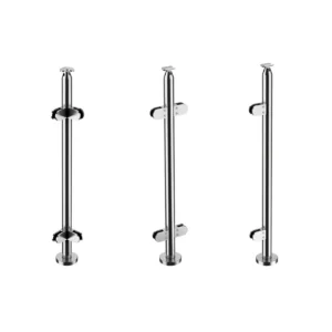
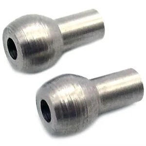
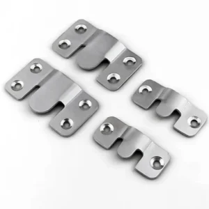
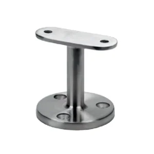
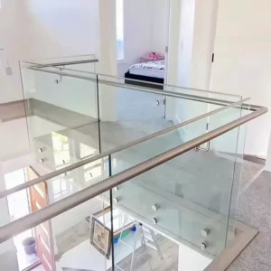
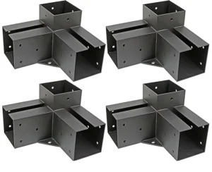
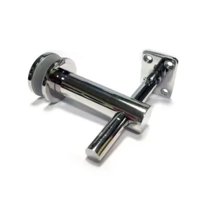
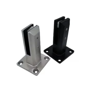
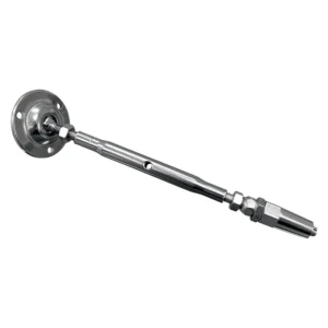
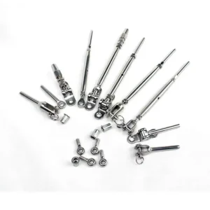
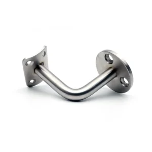
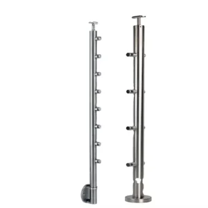
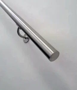
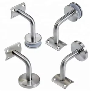
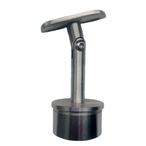
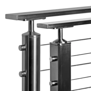
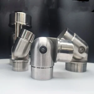
Multi-angle post brackets are for post-to-rail connections where the required geometry changes in more than a simple fixed, level condition. The important questions are which axis moves, what angular window is needed, and how the joint is locked after setting. A marked-up stair, ramp or corner sketch plus post and rail sections is enough to start an enquiry.
Discuss multi-angle post brackets on WhatsApp: +86 185 6601 2949
Separate slope, plan turn and compound geometry
A rail sloping along a stair is a different condition from a rail turning around a landing. A compound transition may involve both. Mark the rail direction in plan and elevation, identify the post face or centreline, and state whether the joint must accommodate one axis or more than one. Do not use one generic angle to describe a connection that changes in two planes.
This distinction also separates a multi-angle bracket from a limited adjustable bracket. A limited bracket may correct one installation angle; a multi-part assembly may provide more than one setting plane. Neither description proves the actual range or freedom of movement for the proposed item.

Confirm the usable angle window
Provide the nominal angle and the tolerance needed on either side, not merely “adjustable.” The proposed configuration should identify minimum and maximum permitted settings, any indexed positions, interference limits and the rail centreline at the selected angle. Check that the rail, post, bracket arm and tightening tool all have clearance at the most demanding position.
If handed parts are required at opposite sides of a stair or corner, show left/right orientation on the drawing. A photographed assembly may appear reversible but still have asymmetric holes, access or bearing faces. The offer should state whether one item covers both hands or separate parts are proposed.
Movement is for setting unless stated otherwise
A pivoting appearance does not mean the joint may articulate during service. For a railing connection, the normal expectation should be a bracket set to the approved geometry and positively locked. If service movement, thermal movement or repeated articulation is required, that is a different engineering duty and must be requested and verified explicitly.
Ask how the proposed bracket resists slip and rotation: clamp faces, pivot fastener, serration, locating pin, multiple bolts or another defined feature. Require access for tightening and inspection. Do not assume that one visible screw is the complete locking system or that tightening torque can be copied from an unrelated bracket.
Match the post and rail bearing surfaces
For the post side, provide round diameter or square width, wall thickness, corner radius where applicable, connection location and any prepared holes, inserts or bosses. Thin hollow sections may need an internal sleeve, backing piece or factory-prepared connection so local tightening does not crush the wall.
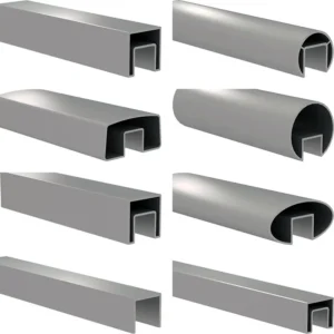
For the rail side, provide the handrail or top-rail profile, outside dimension, slope, centreline and required support form. A flat plate does not automatically match a round rail; a curved saddle must match its intended tube. Also say whether the bracket supports a handrail, top rail or another railing component, because those roles cannot be interchanged from appearance alone.
Choose an assembly route
- Preset at the factory: suitable when surveyed angles and handedness are known; the approved setting should be recorded on the part or assembly drawing.
- Set on site within a defined window: suitable when bounded installation variation remains; provide the setting and locking procedure plus inspection access.
- Fixed bracket made to a measured angle: worth comparing when no field movement is needed and a simpler connection is preferred.
- Compound assembly: use only when plan and elevation changes require separate axes; confirm every interface and avoid treating extra joints as free flexibility.
What a comparable quotation should show
| Field | Required definition | Why it changes the choice |
|---|---|---|
| Meetkunde | Plan angle, slope angle, tolerance and handedness | Determines axes, usable range and interference |
| Berichtinterface | Section, wall, hole/boss/insert and interior access | Determines bearing, fastening and anti-rotation |
| Rail interface | Profile, centreline, saddle/plate and fixing pattern | Determines contact and assembly clearance |
| Locking and work split | Lock method, included hardware, factory preset and site work | Prevents an adjustable pose from being mistaken for a completed joint |
Start with a sketch and finish with location-by-location settings
Send a plan/elevation sketch, post and rail dimensions, approximate quantity, exposure condition and photos of any existing structure. Before order release, the drawing or offer should freeze each location’s angle, hand, post-side and rail-side interface, wall/bearing support, fasteners, locking/anti-rotation method, included parts and factory/site responsibilities. Project-specific structural or regulatory approval remains a system responsibility, not a conclusion drawn from the bracket image.