A wall handrail that looks correctly installed and a wall handrail that is ready for handover are not the same thing. The inspector’s task is to trace what was actually built against what was approved, confirm that the mounting and substrate conditions support the installed hardware, and identify exactly what evidence is still missing before the project can close. Each of these steps depends on a different reference, and skipping the reference does not make the installed run compliant — it only makes the gap invisible until later.
Approved references and inspection records to bring onsite
| Reference or record | Inspection decision it supports | Bewijsgrens |
|---|---|---|
| Approved drawings and location marks | Compare each installed run with the approved location and geometry | The approved project set controls the comparison |
| Specified mounting detail | Check brackets, fasteners, joints, and anchors against the intended mounting detail | Visible presence alone does not establish capacity |
| Governing project requirements | Identify the applicable continuity, clearance, gripping-surface, and termination criteria | Jurisdiction-specific acceptance cannot be inferred from a supplier component |
| Test or inspection records | Identify the records required for inspection and handover | The exact required record set is project-specific |
| Material and finish documents | Check the installed material and finish against the applicable documents | The applicable document set is project-specific |
An inspection without the approved project set is a visual opinion, not a verification. Before walking the run, the inspector needs the documents that define what “correct” means for this specific installation: the approved drawings and location marks that fix geometry and position, the specified mounting detail that defines how brackets, fasteners, and anchors are meant to engage the wall and substrate, and the governing project requirements that set continuity, clearance, gripping-surface, and termination criteria. Without these, an inspector is comparing the installed handrail to memory or to general expectation, which does not hold up at handover.
The distinction matters because a handrail can be physically present, finished correctly, and still fail inspection if it was never checked against the document that controls it. A bracket spacing that looks reasonable may not match the spacing shown on the approved drawing. A termination detail that appears finished may not match the configuration the designer specified for that location. Where the approved set is incomplete or ambiguous onsite, the inspection cannot proceed on assumption; the missing reference has to be resolved before the comparison is meaningful, not worked around.
Test or inspection records and material or finish documents serve a second function beyond geometry: they establish what has already been verified and by whom. If a prior inspection or material certification already covers part of the installed condition, the onsite inspector is confirming consistency with that record, not re-deriving the requirement from scratch. If no such record exists, the inspector is now the first point of verification, and that changes how much scrutiny the visible condition needs. Knowing which records exist, and which are still owed, is part of the reference pack — not a separate administrative task layered on top of the physical inspection. Project submittals covering drawings, material certifications, and related documentation are the kind of record set this comparison depends on, and where that submittal content is incomplete, the inspector is working with a partial basis until it is supplied.
Run geometry, alignment, continuity, and termination checks
| Installed-run checkpoint | Comparison basis | Inspection conclusion |
|---|---|---|
| Geometry and alignment | Approved drawing and location mark | Whether the observed run matches the approved geometry and location |
| Continuity and clearance | Governing project requirements | Whether the observed run meets the criteria selected for the project |
| Transitions and terminations | Approved drawing and location mark | Whether the observed end and transition conditions match the approved configuration |
Checking an installed run means comparing three distinct things against three distinct bases, and conflating them produces false confidence. Geometry and alignment are checked against the approved drawing and location mark — the question is whether the handrail is where the drawing says it should be, at the height and path the drawing shows. Continuity and clearance are checked against the governing project requirements — the question is whether the run, as built, satisfies whatever continuity and clearance criteria the project has adopted, which may vary by project and jurisdiction. Transitions and terminations are checked again against the approved drawing and location mark — the question is whether the end conditions and direction changes match the configuration the designer specified for that location, not merely whether they appear finished.
The reason this separation matters is that a run can pass one check and fail another without any visible inconsistency. A handrail can sit at the correct height and follow the correct path — satisfying the geometry check — while still having a continuity gap at a transition that the project’s governing requirements do not permit. Conversely, a run can satisfy clearance and continuity criteria in general terms while sitting in the wrong location relative to the approved drawing, which is a geometry failure independent of whether it would otherwise be acceptable. An inspector who treats “it looks continuous” as equivalent to “it is positioned correctly” is collapsing two separate questions into one answer.
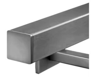
Termination conditions deserve particular attention because they are where fabrication tolerance, field adjustment, and the approved configuration most often diverge from each other without being visually obvious. A termination that has been field-adjusted to fit an as-built wall condition may no longer match the approved drawing’s termination detail, even if the adjustment was reasonable given what the installer encountered onsite. Where the as-built condition differs from the approved condition, the inspector’s role is not to judge whether the field adjustment was sensible but to flag the divergence against the drawing and let the project team determine whether it requires a change or a correction. Roestvrijstalen muurleuningen installed as part of a run are the physical subject of this comparison, but the comparison itself is always against the drawing and the governing requirement, not against the hardware’s general appearance or finish quality.
Brackets, fasteners, anchors, and substrate interfaces
A bracket that is present, finished, and apparently secure tells the inspector very little on its own. What matters is whether the bracket, fastener, and anchor combination matches the specified mounting detail, and whether that mounting detail is appropriate for the substrate actually encountered in the wall. These are two separate checks that happen to be inspected at the same location, and treating them as one check is where mounting inspections go wrong.
The specified mounting detail defines the bracket type, fastener type, anchor type, and spacing intended for the installation. Visual presence of a bracket at roughly the right spacing does not establish that the fastener and anchor beneath it match what was specified, because the parts of the connection that carry load are frequently the parts least visible after installation — the anchor engagement inside the wall, the fastener torque, the bearing condition between bracket and substrate. An inspector confirming “a bracket is here” has confirmed geometry, not capacity. Confirming that the bracket, fastener, and anchor combination was installed as specified, and that it suits the substrate the installer actually encountered, is a different and necessary step.
Substrate condition is the variable that changes which mounting detail is even valid. A detail specified for one substrate type does not transfer automatically to a different substrate encountered in the field; where the wall construction differs from what the design assumed, the anchor type and embedment that were specified may no longer be the correct ones for that location, regardless of how closely the installed hardware resembles the approved detail elsewhere on the run. This is why substrate verification belongs inside the mounting inspection rather than as a separate structural question — the same bracket and fastener can be correctly installed in one substrate and incorrectly installed in another, with no visible difference between the two conditions.
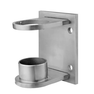
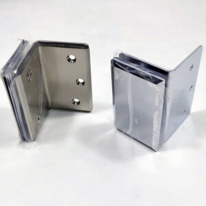
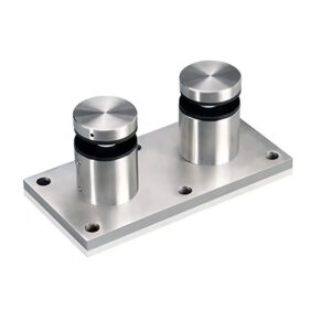
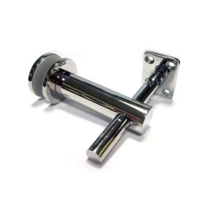
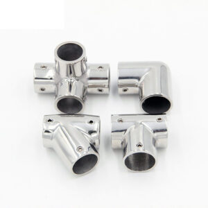
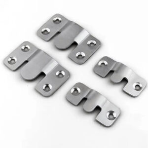
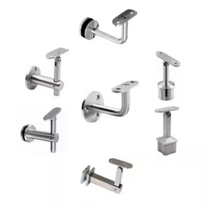
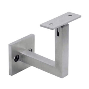
Standaard muurbeugels and the fasteners and anchors paired with them are evaluated against this specified detail and substrate condition, not against general appearance or finish quality. Where the governing project requirements include load or deflection criteria, that evaluation sits downstream of confirming the mounting detail and substrate match — a bracket installed to the wrong detail or into an unsuitable substrate does not become acceptable because the handrail happens to feel rigid when tested by hand onsite. A straight rail joiner and similar connector hardware are inspected on the same logic: the joint is checked against the mounting detail it was specified to use, not against how solid the connection appears on casual inspection.
Joints, finishes, damage, and repair acceptance
| Inspection condition | Evidence or basis to review | Handover disposition |
|---|---|---|
| Gewrichtsaandoening | Specified mounting detail | Determine whether the observed joint matches the specified detail; this alone does not establish system capacity |
| Finish condition | Applicable material and finish documents | Determine whether the observed finish corresponds to the documented requirement |
| Zichtbare schade | Punch item and the exact required repair evidence | Keep the condition open until the project-required evidence is identified and supplied |
| Completed repair | Project-specific repair acceptance evidence | Determine whether the repair is ready for project acceptance |
Joints, finishes, and surface damage each require a different evidence basis, and an inspector who applies one standard across all three will either over-accept or over-reject conditions that need separate treatment. A joint is checked against the specified mounting detail — the same reference used for brackets and anchors — because a joint is a mounting condition, not a cosmetic one. A finish is checked against the applicable material and finish documents, which define what finish was specified and, where relevant, what tolerance applies to variation across the run. Visible damage is checked against neither of these directly; it is checked against whatever repair evidence the project requires before that specific condition can be closed.
This separation has a practical consequence at the point of disposition. A joint that matches its specified detail is not thereby established as adequate for the complete system — matching the detail confirms the joint was built as intended, not that the detail itself is sufficient for the loads or conditions the project requires, which is a separate determination resting with the project specification and designer. An inspector who finds the joint built correctly can close that specific comparison without concluding anything broader about overall system capacity.
Finish discrepancies raise a different question: whether the variation observed is a documented tolerance or a nonconformance, and that distinction depends entirely on what the finish documents allow, not on the inspector’s visual judgment of acceptability. Where the finish documents are silent or ambiguous about a particular condition, the inspector does not have a basis to close that item — the ambiguity needs to be resolved against the document, not assumed in either direction.
Visible damage is the condition most likely to remain open at the time of inspection, because closing it requires evidence that has not yet been generated — a repair has not yet occurred, or has occurred but has not yet been evaluated against the acceptance criteria the project requires for that type of repair. The inspector’s task with damage is not to judge severity but to identify precisely what repair evidence the project requires and confirm that the condition stays open until that evidence exists. A completed repair is then checked against that same project-specific acceptance evidence, not against a general sense of whether the repair looks adequate. Where that acceptance evidence has not been defined for a particular repair type, the repair cannot be closed by visual confirmation alone, regardless of how clean the completed work appears.
Accessibility and project criteria that require qualified confirmation
| Criteria area | Confirmation basis | Acceptance boundary |
|---|---|---|
| Continuity, clearance, and gripping surface | Governing project requirements | Confirm project coverage and the current adopted criteria before concluding acceptance |
| Extensions for covered stair handrails | Applicable project requirements and, where relevant, current U.S. accessibility provisions | U.S. accessibility guidance does not establish that it applies to every project |
| Permanent metal handrail design and load criteria | Project specification, applicable standard, designer, and code authority | A public standard summary or supplier component does not establish field acceptance |
Some of what an inspector checks on a wall handrail run is governed by criteria that the project itself must confirm applies, rather than by a universal standard the inspector can assume. Continuity, clearance, and gripping-surface requirements fall into this category: whether a given criterion applies to this particular run, and what the current adopted version of that criterion requires, depends on project scope and jurisdiction rather than on the hardware installed. The Access Board’s guidance on stairways addresses continuity, gripping-surface, clearance, and extension provisions for covered stair handrails within U.S. accessibility scope, but whether a given project falls within that coverage, and which edition applies, is a determination the project team and code authority make — not something the inspector concludes from the fact that a handrail is present on a stair.
Extensions at the top and bottom of a run are a clear example of why this confirmation step cannot be skipped. An extension requirement that applies to one type of covered stair may not apply to a different run in the same project, depending on how that run is classified and which code edition governs the project. An inspector who applies an extension requirement uniformly across every run, without confirming which runs are covered, risks either flagging a condition that was never required or missing one that was.
Design and load criteria for permanent metal handrails sit in a comparable position. A standard such as ASTM E985 establishes scope and basic design and load/deflection criteria for permanent metal stair, ramp, and handrails, but a public summary of that standard’s scope does not itself establish what the project’s specification requires or what the code authority has adopted for this installation. Similarly, a specification structure such as Bovenste Fossa, 52 graden 00 minuten illustrates how a metal railing specification, submittal, and drawing package can be organized on a government project, but it functions here as an example of structure, not as a requirement that applies to this project by default.
The inspector’s role in each of these cases is to recognize where a criterion requires project-level or jurisdiction-level confirmation and to route that confirmation to the project team and code authority, rather than inferring acceptance from the fact that a compliant-looking component is installed. A handrail that uses hardware capable of meeting a given criterion has not thereby demonstrated that the criterion applies to this run, was correctly selected for this project, or has been verified against the adopted code — those remain separate determinations.
Closeout evidence and punch-list ownership before handover
| Closeout item | Required handover input | Closure question |
|---|---|---|
| Test or inspection records | Exact project-required record set | Are all required records complete? |
| Material and finish documents | Applicable documents for the installed work | Do the documents correspond to the installed material and finish? |
| Punch items | Each open item and its required closure evidence | Which items remain open? |
| Repair responsibility | The responsible project party for each required repair | Who owns each repair before handover? |
| Final handover evidence | The exact evidence required by the project | Is the required evidence complete before handover? |
Closeout is where the preceding checks convert into decisions about what can be signed off and what cannot. The test or inspection records identified at the start of the process need to be confirmed as complete against the project’s required record set — not a general record set, but the exact one this project specified. Material and finish documents need to correspond to what was actually installed, not merely to what was originally specified, since field substitutions or approved changes can shift which document governs a given portion of the run.
Punch items generated during the geometry, mounting, and condition checks each carry their own required closure evidence, and that evidence is not interchangeable across items. An open item involving a mounting detail closes with evidence that the detail was corrected or confirmed against the specification; an open item involving finish closes with evidence that the finish matches the applicable document; an open item involving damage closes with the project-specific repair acceptance evidence described earlier. Treating all open items as closed by a single final walk-through, without confirming that each item’s specific evidence has been produced, leaves the closeout incomplete even if it is marked finished.
Repair responsibility is a distinct closeout question from repair completion. Identifying that a repair is needed, and confirming that a repair meets acceptance evidence, does not by itself establish which project party is responsible for performing or paying for that repair — that assignment depends on contractual and project-specific arrangements outside the inspection itself. Where responsibility has not been assigned, the item remains open from a project-management standpoint even if the physical condition has been evaluated.
The information a buyer or contractor supplies about the installed run — the approved drawings, the mounting details used, the finish documents, the record of prior inspections — is also what a supplier needs when a replacement component, a matching bracket, or a project-matched finish has to be sourced to close a punch item. Where that project information is incomplete, matching a replacement component to the existing run by appearance alone risks a mismatch in mounting geometry or finish that is not visible until installation is attempted. Final handover evidence is, in this sense, the accumulation of every earlier check: the geometry comparison, the mounting and substrate verification, the condition and repair disposition, and the project-specific confirmations, each closed against its own required evidence rather than against a general impression that the installation appears complete.
Veelgestelde vragen
V: What should be checked before access restrictions make the wall interface difficult to inspect?
A: Compare brackets, fasteners, anchors, joints, and the substrate interface with the specified mounting detail and the observed substrate condition. Record any unresolved deviation as a punch item, together with the exact evidence and responsible project party needed for closure.
V: Does a bracket that is present and visibly undamaged prove that the installed handrail has the required capacity?
A: No. Visual presence alone does not establish capacity; review the mounting detail and substrate condition, then confirm which project-required test or inspection records are needed to support acceptance.
V: What should the inspector do when an installed handrail run does not match the approved drawing?
A: Keep the condition open and identify the specific mismatch in geometry, location, alignment, transition, or termination. The punch item should state the required correction or project evidence and who owns the next action before handover.
V: Can inspection of the handrail components confirm accessibility or code acceptance?
A: No. Confirm the project’s governing requirements, jurisdictional coverage, and currently adopted criteria for continuity, clearance, gripping surfaces, and any applicable extensions; acceptance may also require confirmation by the designer or code authority.
V: When is a repaired handrail condition ready for handover?
A: It is ready only when the project-specific repair acceptance evidence has been supplied and the corresponding punch item can be closed against that evidence. Also verify that the applicable material and finish documents match the installed work.