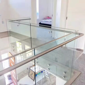
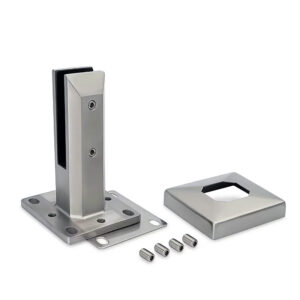
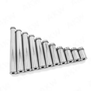
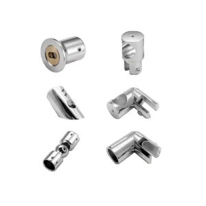
An OEM buyer sourcing wall mount brackets rarely fails at the concept stage; the risk sits in whether a drawing, a sample, and a batch of production parts all describe the same part. Before a purchase order is placed, the project team needs to know which dimensions are fixed by the manufacturer, which depend on the wall or installation, and what evidence at each stage actually proves conformance rather than just resemblance. These questions determine whether repeat orders match the first approved batch or drift part by part.
The Controlled Drawing Package an OEM Bracket Supplier Needs
A controlled drawing is the reference every later step depends on, so its content decides how much ambiguity enters the order. For a wall mount bracket, that drawing needs to freeze the mounting-hole pattern, the projection from the wall, the rail interface, the overall geometry, the material, the finish, and which surfaces are treated as visible versus concealed. Each of these carries a different consequence if left undefined. An unfixed hole pattern creates a coordination problem with the substrate and anchors chosen on site. An unfixed projection changes the clearance available for the rail or glass assembly it supports. An unspecified finish leaves appearance decisions to be made batch by batch, which defeats the purpose of an approved reference.
Where the buyer treats the drawing as a starting point rather than a controlled revision, later disagreements about “what was ordered” have no fixed reference to resolve them against. Where the drawing is frozen at a specific revision before tooling or production begins, both parties can point to the same document when a dimension, a finish call-out, or a surface treatment is questioned. This matters more for brackets than for many other components because a bracket sits at the interface of two systems — the wall structure and the rail or glass assembly — and an ambiguous drawing can shift blame between them without resolving which one is actually out of tolerance.
The drawing package also needs to state which surfaces are inspected for appearance and which are functional only. A bracket’s underside or a concealed face may carry different finish expectations than its exposed face, and if the drawing does not distinguish them, an inspector has no basis for accepting or rejecting a part on cosmetic grounds. This distinction becomes more important as order volume grows, because inconsistent application of an undefined appearance standard across batches produces visible variation even when every part is dimensionally correct.
None of this replaces a project-specific specification. The drawing controls what the manufacturer produces; it does not by itself confirm that the bracket, once installed, performs as part of the finished wall and rail assembly. That confirmation depends on information the drawing does not carry — substrate condition, anchor selection, and the installed load path — which belongs to the next stage of review rather than to the manufactured part.
Critical-to-Fit Dimensions, Tolerances, and Datum References
| Control category | Drawing and inspection treatment | Beslissingsgrens |
|---|---|---|
| Fit-critical bracket dimensions and tolerances | Mark separately in the controlled drawing for measurable inspection. | Applies to the manufactured bracket. |
| Wall, substrate, and installation variables | Keep separate from bracket dimensions and tolerances. | These variables are outside the manufactured bracket. |
Not every dimension on a bracket drawing carries the same consequence if it drifts. Some dimensions determine whether the bracket mates correctly with the rail, the glass fitting, or the fastener pattern; others describe features that have latitude without affecting fit. The practical task for a buyer is separating fit-critical dimensions — the ones that must hold a tight tolerance because another component’s position depends on them — from dimensions that can vary within a wider band without consequence. Where a hole spacing or a mating diameter is marked as fit-critical and tied to a clear datum reference, a supplier’s inspection plan can verify it directly. Where the same dimension is left ambiguous or without a stated datum, two conforming parts can still fail to interchange, because “conforming” was never defined against a fixed reference point.
Datum references matter because a dimension without a stated origin is open to interpretation. A hole position measured from one edge of a bracket gives a different practical tolerance than the same nominal position measured from the opposite edge or from a center feature, once real part variation is considered. For a wall mount bracket, the datum scheme should reflect how the part is actually installed and mated — from the wall-contact face, from the rail interface, or from a mounting-hole centerline — so that the measurement method matches the functional requirement rather than an arbitrary drafting convention.
The distinction that most affects downstream decisions, though, is separating what the manufactured bracket controls from what the installation site controls. Wall condition, substrate type, anchor selection, and on-site alignment are installation variables; they are not properties of the bracket and should not be folded into the bracket’s tolerance stack. A drawing that conflates the two — for example, allowing a mounting dimension to “float” because site conditions vary — makes it impossible to determine whether a nonconforming measurement originates in manufacturing or in installation. Keeping these separate means the bracket can be inspected and accepted on its own terms, independent of the wall it will eventually be fastened to, while the installation-side variables are addressed through site-specific specification rather than through the bracket’s own tolerance.
Where a project involves multiple bracket variants feeding the same rail system, this separation also clarifies which tolerances need to be held tightest: the interfaces shared across variants carry more consequence than dimensions unique to a single configuration, because a shared-interface deviation propagates across every assembly that uses it.
Approval Samples for Appearance and Mating Geometry
| Approval-sample use | Bewijsgrens |
|---|---|
| Appearance and mating geometry | The sample can be used to check both. |
| Installed load capacity and code compliance | One sample does not prove either. |
An approval sample answers a narrower question than buyers sometimes assume. Its function is to confirm that a physical part matches the controlled drawing closely enough in appearance and mating geometry to proceed to production — not to confirm how the bracket will perform once installed and loaded in the finished assembly. Appearance covers finish consistency, visible surface condition, and geometric proportions as produced; mating geometry covers whether the bracket’s interface features — the rail contact, the fastener pattern, the mounting face — align with the components it is meant to join. Both of these can be verified directly against a single sample, by comparison with the drawing and, where relevant, against a mating part.
What a single sample cannot establish is installed load capacity or code compliance. A sample demonstrates that one part, produced under whatever conditions generated that specific unit, matches the intended geometry and appearance. It does not demonstrate that the bracket, once fastened to a given wall substrate with a specified anchor pattern, will carry the loads the finished installation is subject to, nor that the installation meets any code requirement governing the assembly. Those conclusions depend on the substrate, the anchoring method, the loading condition, and often on testing or engineering review that sits outside what a single manufactured component can prove by itself.
This distinction changes what the buyer should request at the approval stage versus later in the project. At approval, the reasonable ask is a sample checked against the drawing for dimensional and appearance conformance, ideally alongside the mating component it will connect to, so that fit can be verified physically rather than assumed from drawings alone. Where the project also requires confirmation of load performance or regulatory compliance, that evidence needs to come from a separate source — testing, engineering calculation, or documentation scoped to the installed assembly — and should not be inferred from the fact that a sample was approved.
Where a project changes the mating component after a bracket sample has already been approved — a different rail profile or a different glass fitting, for instance — the approval no longer covers the new interface, and mating geometry needs to be re-checked against the revised part before production proceeds on the original sample’s basis.
Inspection Points, Records, and Disposition Rules for Each Batch
An approved drawing and an approved sample only carry value if the production batches that follow are checked against them in a way that produces a decision, not just an observation. Each requirement on the purchase order needs to map to a specific inspection point — a dimension, a finish attribute, a mating check — along with a record format that captures what was measured and a disposition rule that states what happens when a measurement falls outside the accepted range. Without this mapping, an inspection can generate data without generating a decision, leaving nonconforming material in an undefined state between rejection and acceptance.
The record format matters because it determines whether a discrepancy can be traced back to a cause. A record that only states “pass” or “fail” against a requirement gives no information about how close a batch ran to a tolerance limit, whereas a record that captures the actual measured value against the specified range lets both sides see whether a process is drifting before it produces an outright nonconformance. This becomes more relevant across repeat orders, where a dimension that passes inspection but trends toward one tolerance limit batch after batch signals a process issue worth addressing before it produces a rejected lot.
Disposition rules need to be set before production starts, not negotiated after a nonconformance is found. A rule might call for full rejection of an affected lot, sorting to separate conforming from nonconforming units, or another resolution — but whichever rule applies, it should be tied to the specific inspection point in advance so that a deviation has a predetermined path rather than becoming a case-by-case negotiation. This is particularly relevant for fit-critical dimensions, where a disposition decision affects downstream assembly schedules for the rail or glass system the bracket feeds into.
Where inspection is limited to a sampling plan rather than full inspection of every unit, the buyer needs to understand what that sampling approach does and does not detect — a plan built around routine dimensional variation may not catch an isolated defect, and the disposition rule for a sampling-based inspection should reflect that difference from a full-inspection approach.
Packaging and Identification Controls for Repeat Supply
Packaging and identification are easy to treat as administrative details, but for a component that recurs across multiple orders and potentially multiple projects, they are what keeps the approved part traceable once it leaves the inspection record and enters a job site. A wall mount bracket that looks similar to a prior revision but is not identified as such can be installed in place of the correct part without anyone noticing the substitution until a mismatch surfaces downstream — a mounting hole that doesn’t align, a finish that doesn’t match, or a projection that changes the rail’s final position.
Identification needs to tie each unit or batch back to the drawing revision it was produced against, so that if a revision changes mid-project, older stock and newer stock are not mixed without anyone being aware of which version is which. This matters most where a project spans a long enough timeline that a drawing revision could occur between the first order and a repeat order, or where multiple bracket variants share a similar external appearance but differ in an interface dimension that is not visible without measurement.
Packaging itself protects finish and geometry between production and installation. A bracket with a controlled visible-surface finish can be affected by how it is packed, handled, and stored before it reaches the site, and packaging that does not account for this can turn a conforming part into a nonconforming one before it is ever installed. Where a project specifies a particular finish as visually critical, the packaging approach should be evaluated as part of the overall control, not treated as separate from the finish requirement itself.
For repeat orders specifically, identification also supports comparing a new batch against a previously accepted one without relying on memory or visual impression alone. A label or marking scheme that records the drawing revision, and where relevant the batch or lot, gives the buyer’s receiving process a basis for confirming that what arrived matches what was approved, rather than assuming continuity because the part looks the same as before.
Revision Control Before an Approved Design Changes
Once a drawing and a sample are approved, any change to either needs a defined path rather than an informal adjustment folded into the next production run. A revision might originate from a design change requested by the buyer, a manufacturing process adjustment proposed by the supplier, or a correction to an error discovered after approval — but regardless of origin, the same three questions apply before the change proceeds: which dimensions does the change affect, does the existing approval sample still represent the part, and does the inspection plan still test the right points.
Identifying the affected dimensions first matters because a change made for one reason can shift a dimension that was not the intended target. A material substitution, for instance, can change how a feature holds tolerance during production even if the nominal dimension on the drawing is unchanged, which means the fit-critical dimensions need to be reviewed against the new condition rather than assumed to be unaffected simply because the drawing wasn’t redrawn.
The sample status question follows directly: if the change affects a dimension or feature the original approval sample was checked against, that sample no longer represents the current design, and a new sample needs to be reviewed before the change is treated as approved for production. Continuing to reference an outdated sample as the standard for an updated drawing reintroduces the same ambiguity that a controlled drawing was meant to eliminate.
Finally, the inspection plan needs to be checked against the revised drawing to confirm that it still measures the dimensions that matter under the new configuration. A change that adds a new fit-critical interface, or removes one, changes what the inspection plan needs to capture — an inspection plan built for the prior revision may test dimensions that are no longer relevant, or fail to test one that is now critical.
Where a project favors design stability over cost or lead-time flexibility, the stricter path is to hold the revision until all three questions are resolved and documented before the next batch starts. Where a project accepts a documented interim risk to meet a schedule, the change can proceed with the affected dimensions, sample status, and inspection plan explicitly flagged as open, rather than silently carried forward as if nothing changed.
Veelgestelde vragen
V: What should be fixed before requesting an OEM wall bracket quotation?
A: Use one controlled drawing revision that defines the mounting-hole pattern, projection, rail interface, geometry, material, finish, and visible surfaces. Keep unresolved wall, substrate, and installation variables separate so the quoted manufacturing scope and later acceptance refer to the same baseline.
V: How can buyers compare two suppliers’ tolerance proposals fairly?
A: Compare both proposals against the same drawing revision and the same list of fit-critical characteristics. For each purchase requirement, confirm the measurable inspection point, the record format, and the disposition rule that will apply if the result falls outside the requirement.
V: What should approval of an initial sample authorize?
A: Authorize only the appearance and mating geometry that were actually checked against the controlled drawing. Keep installed load capacity and code compliance open until they are supported by separate project-specific evidence rather than treating one sample as proof.
V: If a delivered bracket does not fit, where should the investigation start?
A: First compare the manufactured fit-critical dimensions with the controlled drawing. Then assess the wall, substrate, and installation conditions separately so a site variable is not mistaken for a bracket-manufacturing issue, or vice versa.
V: How should an approved design or process change be handled before repeat production?
A: Identify the affected dimensions, confirm whether the approval-sample status changes, and update the inspection plan before the next batch. Tie the applicable drawing revision and identification controls to that batch so the buyer can verify which approved version was supplied.