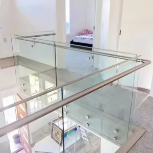
Start with the largest complete section the transport path and site will accept, and split only where you must. The right division between continuous and sectional handrail supply comes down to three overlapping constraints: how far the rail can travel without damage, what access the site allows, and where a joint can land without disrupting either the grip surface or the finish. If the whole route can be preassembled in the shop and delivered in one piece, that is the right starting point. If it cannot, the split decisions that follow deserve as much engineering attention as the handrail geometry itself.
Choose the Largest Practical Supply Sections
The first question is not how to cut a long run into equal pieces — it is whether a cut is needed at all.
A shop-completed section arrives with its geometry set, its welds dressed and its surface finished under controlled conditions. You avoid a site joint entirely, which means no fit-up tolerance to manage, no field-worked surface to blend and no additional hardware to procure, fit and check. Federal metal-railing procurement guidance treats shop preassembly and disassembly only as necessary for transport and handling — meaning the default is the largest practical unit, with splitting reserved for cases where the route genuinely demands it.
Related Products
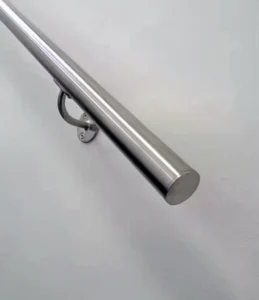
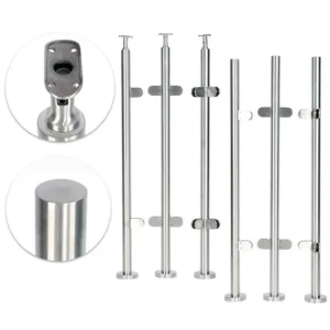
- 连续圆形钢管 — Review tubing for a route supplied as long lengths or coordinated sections.
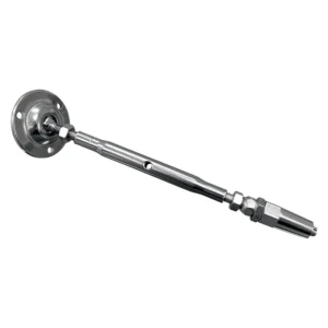
- 无缝钢轨连接 — Review a connection option where the visible junction needs coordination; confirm its actual detail.
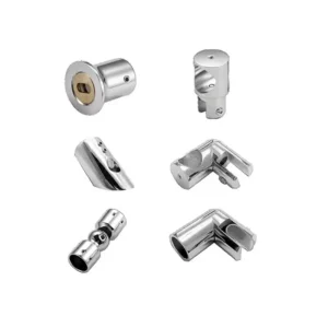
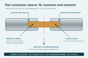
- 轨道连接器套管 — Check a candidate section joint against actual mating dimensions and assembly access.
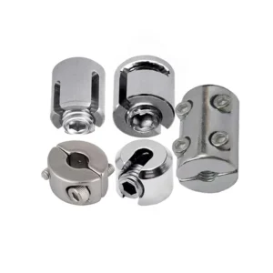
- 通用导轨连接器 — Compare connector candidates for a route junction; the product name leaves compatibility to confirmation.
- 连续墙扶手系统 — Review a wall-supported continuous-route option before selecting its ends and joints.
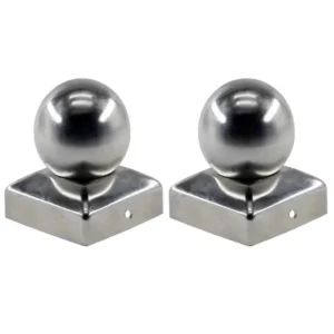
- 接线柱轨道组件 — Check components at the end of a post-supported rail segment.
Shop preassembly is therefore the right starting point unless a constraint upstream or downstream forces a different answer. Identify that constraint first. A section that can be positioned without breaking is worth more than a neatly modular shipping schedule that creates three unnecessary joints.
Where splitting is necessary, resist the instinct to divide by equal length. The useful question is: given the access conditions, what is the largest section that can still reach its installation position? That answer sets your maximum unit size, and the number of sections follows from it.
Test the Transport and Access Envelope
A section that fits on the delivery vehicle is not automatically a section that can reach the fixing position.
Delivery length is only the first filter. After the vehicle, the section must move through every gate, corridor, stair opening and landing it encounters before it reaches the wall or posts. A long rail that navigates the street access and clears the building entry can still be stopped by a 90-degree turn in a stairwell or a reduced-height plant room. Record the full movement path — not just the straight clear lengths, but every change of direction, every door or threshold it must pass through, and the minimum turning radius at each point.
Transport and Site Access Checks
| Movement stage | Check on the actual route | Supply implication |
|---|---|---|
| Delivery vehicle | Whether the proposed preassembled section fits the transport envelope | Retain a large section only where transport permits it |
| Building entry and turns | Whether the section can pass the entry points and turn along the access path | Split the supply to suit the limiting site access envelope |
| Final movement to installation | Whether the section can reach its intended position | Confirm the whole movement path before fixing section lengths |
The controlling dimension is the tightest point on the full movement path, not the longest straight section of the finished route.
Consider a project where a 6-metre stair handrail fits the delivery flat-bed without difficulty and clears the main building entrance. The limiting constraint turns out to be a half-landing with a 1.2-metre corridor before the final flight. That corridor — not the truck, not the door — is what sets the maximum section length. Missing it at the planning stage means arriving with a section that physically cannot be turned into position, regardless of what the packing list says.
Document the access envelope as a set of labelled checkpoints on your site plan: vehicle offload point, building entry, corridor runs, turns and final installation zone. Each checkpoint should record its clear dimension and any height or width restriction. When you send this to the supplier, you are not just describing a problem — you are defining the actual constraint that sets the cut list.
Place Reassembly Joints Deliberately
Choosing sectional supply is a decision; placing the joints is a separate, equally careful one.
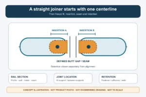
A transport split creates a physical interface at the join. That interface will be visible, touched during use and exposed to whatever the environment delivers — so its location is not a leftover of the shipping arithmetic. Locate each proposed joint on the route drawing before you finalise the cutting list, and confirm the joining method at the same time. A sleeve connector, an internal spigot and a butt-welded field joint each require different cut-end preparation, different site access for assembly, and different tolerances at the mating faces.
Joint position also interacts with the rail geometry. A joint that lands mid-flight on a straight run is easier to fit and finish than one that lands at a bend, a return end or immediately above a post. Where the route includes curved sections or returns, work backward from those features when you place the cut: a straight run gives you the most tolerance for fit-up and the cleanest result for finishing.
Where a continuous gripping surface is required — on a stair route subject to accessibility requirements, for example — specify continuity as an installed result, not a shipping condition. Supply sections are not the same thing as handrail terminations, and a well-placed sleeve joint that is smooth and flush under the hand satisfies a continuity requirement in a way that an abrupt end cap or a poorly fitted connector does not. Evaluate each proposed joint against that installed result before committing the cut list.
For every joint, also confirm who supplies the mating hardware. A cut end needs its matching fitting: the outside profile of the tube, the inside bore and the connection geometry all determine whether the two sections can actually join. Tube dimensional standards give you a reference for profile and wall thickness, but they are not a compatibility rating for a rail connection. State the fitting specification explicitly in the supply document and assign responsibility for each component before fabrication begins.
Related Reading
- 为基于项目的栏杆硬件采购定制不锈钢扶手系统 — Prepare the project information and supply scope before requesting a coordinated package.
- 不锈钢栏杆系统:买家必须确认的管材公差、表面质量和连接器兼容性 — Check the neighboring tube, finish and connector interfaces before accepting a substitution or final package.
- 不锈钢栏杆切割、焊接和安装后的施工现场清洁规则 — Review the adjacent cleaning discussion when cutting or joining leaves site work; confirm the chosen application.
Match Section Ends and Finish Work
Every cut end creates two things: a mating face and a finishing task.
If the joint leaves grinding, polishing or passivation work to be done on site, that work is part of the installation scope whether or not the supply documents say so. A shop-finished rail surface treated to a specified grit or texture can change character at a field-worked joint if the site work uses different tooling or sequence. The result is a visible line across the grip surface — not a structural problem, but a finish problem that is difficult to correct after the section is fixed in position.
Agree the finish reference, the surface-treatment method and who is responsible for each before the first section leaves the shop.
ASTM A380 covers cleaning and passivation of stainless steel assemblies within an agreed scope. What it does not do is guarantee a universal result or define a single treatment sequence that applies to every field condition. The practical implication is straightforward: any field work at a joint needs to be scoped, assigned and referenced against the same finish standard used in the shop. If that scope lands with the installer, it belongs in the installation package. If it stays with the fabricator — perhaps through a site visit or a supplied finishing kit — that arrangement needs to be confirmed in the supply agreement, not discovered after the sections arrive.
Where the rail runs through a coastal or high-humidity environment, the exposed joint geometry matters more. A poorly sealed sleeve or a gap at a butt joint can trap moisture and contaminants against the tube surface. Design the joint to drain or vent, and confirm that any internal connector material is compatible with the surrounding stainless grade. Sealant or gasket specification, where used, should appear in the assembly document alongside the joint type.
Schedule Sections for Site Assembly
A complete section plan includes not just what ships but where each piece goes and how it connects to its neighbours.
When several similar sections arrive for different flights, elevations or return runs, a quantity-only packing list becomes a liability. Sections that are close in length, or that have mirrored end geometries, are easy to confuse on a busy site. Give each section an installation location, an orientation and a matching-end identifier that appears on both the drawing and the shipping schedule. A simple alphanumeric mark — stamped, tagged or marked with a durable label — connects the piece in the crate to its position on the route drawing and to the specific end it must meet.
Where part of the route is confirmed and part remains dimensionally unresolved, release them on separate schedules. Fabricating and shipping the confirmed sections preserves the shop work already done without forcing a decision on a junction that is not yet fixed. The cut list must clearly identify which interface is still open — not so the unresolved end sits unmarked in a pile, but so it is tracked as a defined coordination item with an owner and a resolution date.
ESANG’s section planning process can be configured to reflect this split: confirmed sections released for production, uncertain interfaces flagged with a hold status and a reconfirmation trigger. That separation keeps the project moving without committing material to a dimension that may change.
A usable section schedule contains, for each piece: the installation zone, the section identifier, the left- and right-end descriptions (termination type, mating fitting reference or hold status), the finish specification, and the assembly sequence where order affects access. When you bring this document to the supplier conversation, the fabrication scope is already defined. What remains is confirming the material grade, the finish reference, the hardware pairings and the delivery sequence — the variables that ESANG needs to turn a section plan into a cut list and a production release.
Before that conversation, have ready: the route drawing with section boundaries and joint locations marked, the access envelope checkpoints with their clear dimensions, the finish specification and the responsibility split for any field finishing, the connectivity hardware specification for each joint type, and a clear note on which interfaces are confirmed and which are still open.
References
- Access Board Guide – Chapter 5: Stairways — Review the stairway-specific continuity and end provisions where US accessibility requirements apply.
- UFGS 05 52 00 金属栏杆 — See an editable metal-railing specification example for drawings, assembly and supply interfaces; adapt it to the project.
- ISO 1127:1992 Stainless Steel Tubes – Dimensions, Tolerances and Conventional Masses — Check the dimensional scope for stainless tube; it supplies no assembly compatibility or load rating.
- ASTM A380/A380M-25 Cleaning, Descaling, Pickling, and Passivation of Stainless Steel — Review cleaning and surface-treatment scope when joints or cutting create fabrication work; agree the applicable procedures.
常见问题
问: What should happen if one labelled section is damaged in transit?
A: Identify the affected location and mating-end references before ordering a replacement. Preserve the undamaged partner details so the replacement is made for the actual interface rather than just the original overall length.
问: Can the same split plan be reused for a second building?
A: Reuse its approach, then check the new delivery path and route geometry. Identical rail profiles do not mean the access turns, section lengths or installation sequence are identical.
问: How should spare sections be distinguished from installation pieces?
A: Separate them on the packing schedule and show the location or interface they can replace. An unassigned spare should not carry a normal installation-location mark that invites it to be fitted in the route.