Specify the centerline, sleeve fit and seam before choosing a straight rail joiner
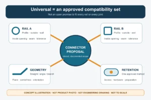
A straight rail joiner connects two rail ends on one intended centerline. Its job may be to extend a run, divide a long rail for transport or replace a damaged splice, but “straight” does not describe the mating size, insertion, retention or support condition. The purchase decision begins with coaxial alignment and the rail section, then fixes how the joint is assembled and held.
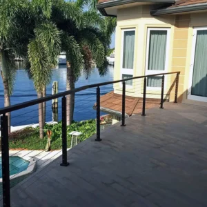
Send a photo or rough section, one measured rail dimension, the proposed splice location and an approximate quantity to start. A drawing or sample may still be needed before manufacture because an exterior view cannot reveal the inside opening or weld seam.

Keep the two rail axes coaxial
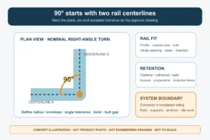
Draw one reference centerline through both rail sections and define the permitted lateral offset, angular misalignment and rotation. For round rail, rotation may matter because of finish direction, holes or nearby brackets. For square or rectangular rail, even a small twist creates an obvious step at the seam. A joiner can fit inside both rails and still fail the visual or graspability requirement if coaxiality is not controlled.
Show whether the splice is concealed, flush or intentionally collared. State the acceptable butt gap and step, and identify any requirement for continuous grain or polish. For a graspable handrail, call out the maximum permitted projection at the joint rather than leaving it to site interpretation.
Choose the splice concept to suit the rail and access
| Splice concept | Selection basis | Trade-off to record |
|---|---|---|
| Internal sleeve/spigot | Clear inside opening, wall thickness, weld-seam clearance and sufficient insertion on both sides | Cleaner exterior, but the rails must slide over the joiner and internal variation controls fit. |
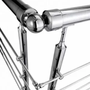
| External collar/socket | Outside profile, visible envelope, fastener access and accepted surface step | Easier to see or access, but the collar and seam remain visible. |
| Supported splice | Joint positioned at a post, bracket or other defined support | Support can control alignment, but its exact interface and assembly order must be coordinated. |
| Prepared welded splice | Joint preparation, welding location/process, distortion control and finish restoration | Can produce a continuous appearance, but hot work and finish work become explicit scope. |
The rail section controls the fit
Round rail
Provide actual outside diameter, wall thickness and minimum clear inside diameter. An internal longitudinal seam, coating or out-of-round condition may reduce the opening. If the joiner uses an external collar, identify the permitted outside step and seam.
Square or rectangular rail
Provide outside width and height, wall thickness, inside opening, corner radii and seam position. Two rails with the same outside label can have different internal corner geometry. Mark orientation so the joiner does not permit one rail to rotate relative to the other.
Existing or unknown rail
Use actual measurements or a sample. A photo and one known dimension can start the match, but the proposal should keep the unverified inside fit open until the section or sample is checked.
Insertion and butt gap belong on the drawing
Set the engagement length on Side A and Side B independently. The rails need square, deburred ends unless another preparation is shown. Mark the finished butt gap and identify whether the joiner has a center stop or whether installers must set position from a dimension. If the sleeve bottoms against a weld seam or internal obstruction, the rail may stop short and move the splice away from its intended support.
Do not use a large gap to compensate for incorrect rail length without approval. The gap can expose the joiner, interrupt the grip surface and alter how retention loads are transferred. Conversely, a zero-gap detail may be impossible if the assembly needs room for adhesive, welding or thermal movement; state the intended function instead of assuming.
Select retention as part of the joint—not as an accessory
| Method to evaluate | Fields to confirm | Installation consequence |
|---|---|---|
| Set screw / through-fastener | Hole pattern, thread or fastener, access side, torque/process and included hardware | Rail drilling and tool access must remain possible after adjacent parts are placed. |
| Adhesive bond | Fit clearance, preparation, adhesive/primer, coverage, cure and temporary restraint | Surface condition and cure control become part of site acceptance. |
| Welding | Factory/site location, joint preparation, process, distortion control and finish restoration | Hot-work permission, qualified work and refinishing must be assigned. |
| Swage or other formed retention | Compatible rail/joiner geometry, tooling and inspection method | Special tooling and irreversible preparation may affect replacement and site sequence. |
These are possible specification routes, not a claim that every route is available for every joiner. The quotation should identify one proposed method and list its hardware or consumables.
Plan the assembly sequence before the rail is fixed
An internal sleeve may need to enter one rail first and then slide into the second. An external collar may need access to fasteners from a particular side. A supported splice can become inaccessible after the bracket or post head is closed. Mark the available movement, tool path and order of operations on the installation sketch.
If both rails are already fixed, send photos of the available clearance and explain which parts can be released. Do not assume a joiner can be retrofitted just because its final position is visible.
A standard joiner is not an undefined expansion joint
A straight joiner normally creates a fixed aligned splice after final assembly. If the project needs movement, define the direction, displacement, joint gap, support arrangement and service conditions. A separately designed movement detail may be required. Do not leave a sleeve loose or omit retention in the hope that it will absorb thermal expansion.
Divide factory work, site work and system responsibility
- Factory proposal: joiner form, mating dimensions, engagement, holes/threads, proposed material/finish, retention set and marking.
- Rail preparation: list whether rails are supplied, cut, drilled, slotted, welded or finished; otherwise those items remain separate.
- Site installation: as-built measurement, trimming, deburring, drilling, bonding/welding, alignment, support/anchor installation and final inspection need an owner.
- Included package: separate the joiner body, screws/pins/inserts, adhesive or welding consumables, rail sections, brackets, posts, spares and packing.
- System performance: the joiner, rails, supports, fasteners, anchors, substrate and workmanship act together. A joiner fit or material label does not prove the completed handrail or guard.
Information that turns an inquiry into a comparable offer
Start with what is available:
- overall and close-up photos, splice reason and approximate quantity;
- rail profile, outside dimensions, wall thickness, inside opening, corner radii and weld seam;
- splice location, nearest supports, system role and whether the rail is new or existing;
- internal sleeve, external collar or supported-splice preference;
- insertion on both sides, intended butt gap, alignment/step tolerance and finish direction;
- retention preference, access, available tools and hot-work/adhesive restrictions;
- exposure, proposed material/finish basis and configuration-specific evidence required.
The resulting quotation should state the exact mating envelope, engagement, retention, rail preparation, seam, included items, exclusions, approval sample/drawing and commercial basis. A low body-only price is not equivalent to a prepared and retained splice package.
常见问题
Can I select a joiner from the rail outside size?
Only for some external concepts. An internal sleeve also needs the inside opening, wall thickness, corner geometry and seam clearance.
How much of the joiner should enter each rail?
There is no single value to assume. Engagement must be shown for the proposed joiner, rail section, retention and system role. Ask for Side A and Side B dimensions on the drawing.
Should the two rail ends touch?
Only if the approved detail says so. Define a butt gap that suits the connector stop, retention, finish and any specifically designed movement requirement.
Can adhesive replace screws or welding?
Not automatically. If bonding is proposed, the joint geometry, preparation, adhesive system, cure and installation control must all be defined for that configuration.
Can the splice sit between supports?
That is a system decision, not a visual one. Show the support spacing, rail role and project criteria so the proposed splice location can be reviewed.
Does a straight joiner rating apply to the complete railing?
No. Completed performance depends on the joined rails, retention, supports, anchors, substrate and installation as well as the joiner.
Send one section and one splice location
A rough sketch and one measurement can begin the review. Before approval, the proposal should make coaxiality, rail fit, insertion, butt gap, retention, assembly sequence, support condition, finish and scope split explicit.