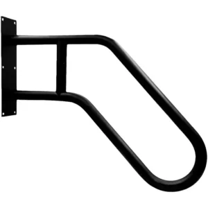
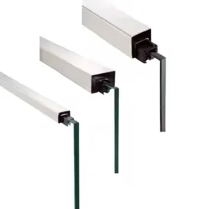
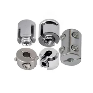
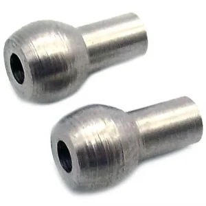
Extended reach wall brackets place a handrail, rail or panel-support interface farther from the finished wall when a reveal, cladding zone, service or other obstruction prevents a standard projection. The projection is not a cosmetic dimension: a longer arm changes leverage at the wall connection. Send a section showing the wall, obstruction and target interface centreline so the proposed bracket can be reviewed as part of the complete attachment.
Request an extended reach bracket review
Measure the reach from the structural reality
Define projection from a named reference plane—normally the finished wall face or verified structural backing—to the centreline of the rail, clamp or panel-support interface. Include cladding, waterproofing zones, trims, service gaps and any construction tolerance. A dimension taken from an unfinished wall can produce a bracket that is too short after finishes are installed.
- Clearance: record the obstruction envelope and the minimum gap needed for installation, use and cleaning.
- Interface centreline: state where the rail or supported component must finish, rather than requesting a vague “long” bracket.
- Orientation: show whether the arm is horizontal, vertical or used in another approved position.
- Repeatability: identify whether one reach applies throughout or whether several defined lengths are needed.

Longer projection changes the wall-side demand
For the same applied force, moving the interface farther from the wall increases the moment at the bracket and anchor group. That is why a standard bracket cannot be lengthened by appearance alone. The proposed arm geometry, wall plate, anchors, backing and bracket spacing must be assessed together for the actual reach and load case.

Choose the outer interface separately from the reach
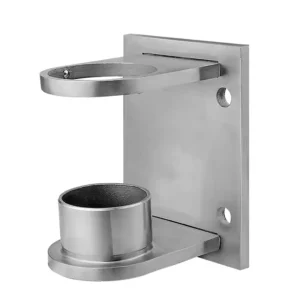
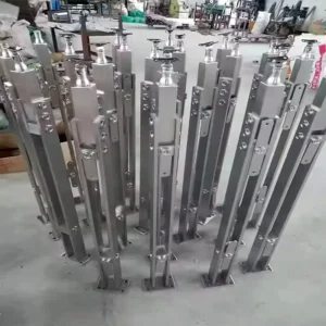
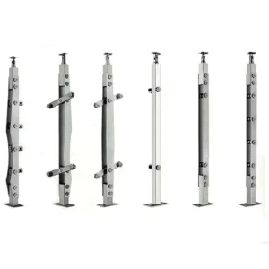
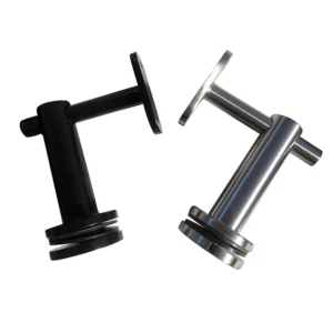
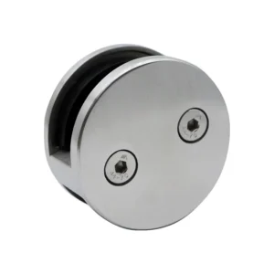
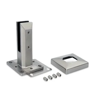
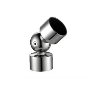
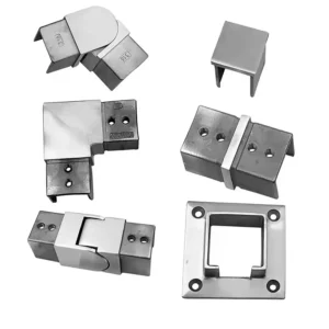
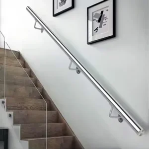
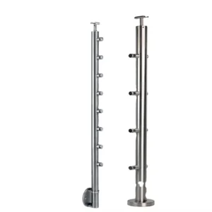
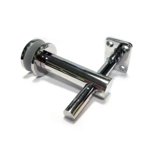
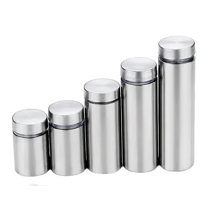
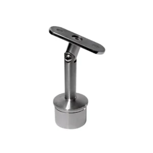
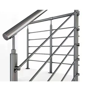
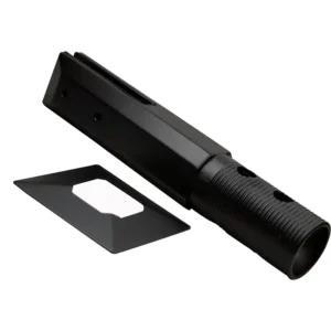
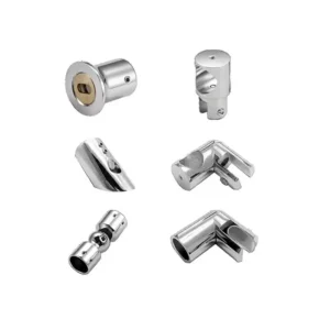
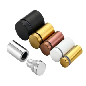
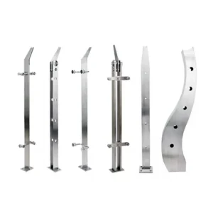
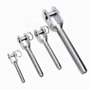
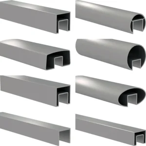
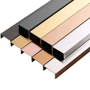
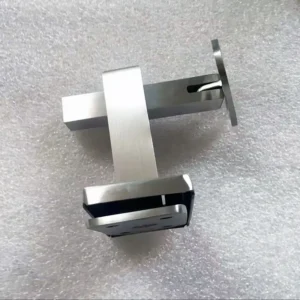
The public reference images show elongated stems with square or rounded clamp-style heads. Those visible forms may help identify an aesthetic or mating direction, but they do not prove compatibility with a specific glass panel, handrail or rail. State the supported component, profile or panel build-up, contact shape, required liners or pads, hole pattern and installation orientation.
For a panel-support interface, confirm panel type and thickness, edge treatment, hole or no-hole condition and the other supports in the system. For a handrail or rail connection, provide the profile, local wall thickness or reinforcement, saddle/contact shape and bracket-to-rail fasteners. The bracket must not be treated as the only structural component in either system.
Coordinate anchors with the substrate and edge conditions
The responsible project party must confirm the structural backing behind finishes, available edge distances, anchor group, drilling depth or through-bolt access and the condition of the existing structure. Cladding and insulation may need non-load-bearing spacers while the load path continues to structural backing. The quote should make clear whether spacers, anchors, backing plates and sealing work are included or site-supplied.
Make extended-reach offers comparable
| 字段 | Required record | 为何这很重要 |
|---|---|---|
| Projection | Reference plane to interface centreline | Controls clearance and wall moment |
| Duty | Handrail, guard or panel role; load directions; bracket spacing | Prevents a decorative form being used as a structural assumption |
| Wall attachment | Substrate, backing, wall plate and anchor arrangement | Makes the load path reviewable |
| Outer interface | Rail/profile or panel details, contact head and mating hardware | Avoids a bracket that reaches the line but cannot connect |
Factory and site split
The factory proposal can define the bracket body, exact reach, outer head or saddle, proposed finish and included assembly hardware. Site work normally verifies the reference planes and dimensions, prepares structural backing, selects or approves anchors, installs any spacers or seals, sets out the common line and inspects the completed attachment. The quote should state which drawings or verification documents are expected before production.
Start with a section, even if dimensions are preliminary
A sketch or marked-up photo can start the conversation. Include the obstruction depth, target interface line, wall construction, rail or panel details, estimated spacing and quantity, environment and any load or approval criteria. Before production, the proposed drawing should freeze all of these fields plus included fasteners and explicit exclusions.