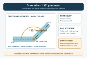
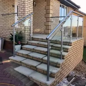
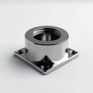
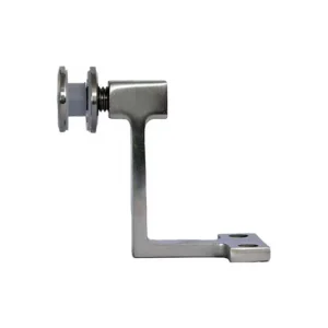
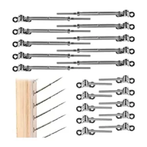
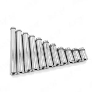
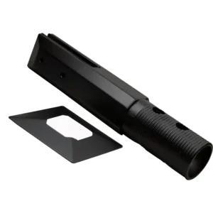
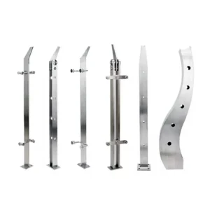
Corner post cable hardware resolves what happens when one cable-railing run meets another direction. The corner can terminate two independent runs, use a confirmed continuous-routing detail, or use a multi-post layout. It must not be treated as permission to pull cable around any post edge. Choose the routing strategy first, then match the corner hardware, post section, cable and access.
Discuss corner post cable hardware on WhatsApp
Choose between termination and a confirmed continuous turn
The most important corner decision is whether each direction is an independent cable span or whether a cable continues through the turn. Independent spans terminate on adjacent faces of the corner and can be adjusted separately. A continuous turn uses fewer terminals but makes cable route, guide geometry, bend condition and total run behaviour interdependent. It is appropriate only when the selected system confirms the corner detail.

Independent terminated runs
Use this route when each railing direction needs its own fixed and tensioning ends, when the corner angle or post geometry does not provide a confirmed cable path, or when separate maintenance and adjustment are preferable. The post must provide suitable bearing surfaces and internal clearance for hardware on both faces.
Confirmed continuous corner route
Use only a guide, saddle, sleeve or other corner component that is matched to the cable construction and post layout. Ask the response to identify the allowable route, guide contact, cable entry and exit angles, required post arrangement and where final tension adjustment occurs. A fitting advertised as adjustable or pivoting does not automatically prove that it is a continuous-cable corner guide.
Double-post or separated corner
Two posts can create room for a controlled route or separate terminations, but the actual spacing, anchorage and cable path still need to be designed for the project. A double-post concept from one system should not be copied into another without checking the post and hardware interfaces.
Corner post geometry controls the hardware
Send a plan view showing the included corner angle, cable directions and post orientation. Also provide the post shape, outside size, wall thickness or solid depth, hole locations and access from the top, inside or rear faces. Round, square and fabricated corner posts create different bearing faces and internal clearances.
A single corner post carrying terminals on two faces can become crowded inside. Threads, nuts, cable tails and tools may collide even though each fitting fits the post by itself. Hole rows can also intersect or leave too little material between openings. These conflicts must be checked before machining.

Ask for the bearing method on each face: flat washer, shaped seat, plate or another proposed component. The seat must fit the post surface and provide room for tightening without distorting a thin wall. If reinforcement is required, the proposal should identify its interface and whether it is included or supplied by the post fabricator.
Build each span around a fixed end and a tensioning end
For independently terminated runs, mark the fixed and tensioning end of every span. A corner post can carry fixed ends, tensioning ends or one of each, but that choice changes the exposed hardware and service access. It may be better to move the adjustment to another terminal where the installer can hold, tighten and trim the fitting safely.
For a continuous corner route, identify the fixed and tensioning ends of the entire cable run and confirm that adjustment can move through the planned corner guide. Excess friction or a tight bend can prevent tension from distributing as expected. Do not assume that tightening one terminal automatically equalises every segment around a turn.
Cable construction and diameter affect the corner route
Provide nominal cable diameter and strand construction. The cable’s stiffness and outer surface affect how it enters a guide, follows a change in direction and responds to field cutting or termination. The corner component, fixed terminal and tensioning terminal must all be confirmed for the same cable input.
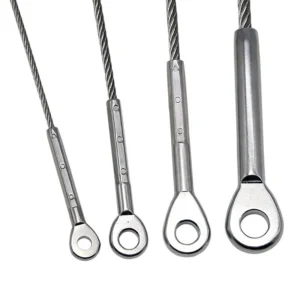
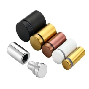
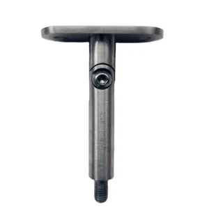
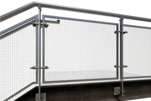
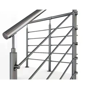
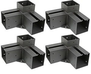
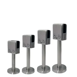
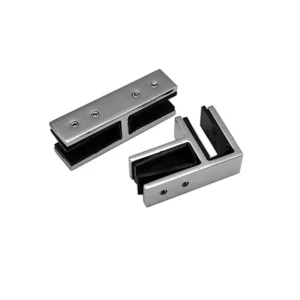
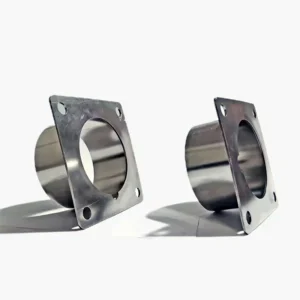
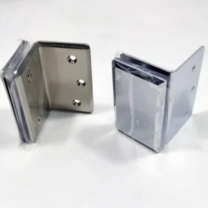
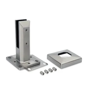
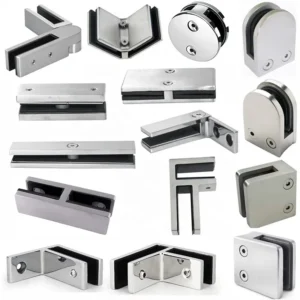
A mismatch can produce strand damage, local flattening, a cable that springs away from the intended route, a fitting that cannot grip, or a terminal that lacks adjustment after the cable is cut. A product photograph cannot confirm these relationships. The current ESANG feature image shows several visible angular and pivoting hardware forms, but it does not by itself define their internal structure, cable range, material, angle range, load or complete system role.
Resolve stair and compound-angle corners explicitly
A level corner changes direction in plan. A stair corner can change both plan direction and vertical angle. This compound geometry cannot be reduced to a generic “90-degree corner” description. Send the plan angle, stair rise/run or measured cable pitch, post lean if any, landing transition and the intended cable centreline on every face.
For independent stair spans, the terminal or seat on the sloped side must align with the cable angle. For any proposed continuous transition, the route must be specifically confirmed for the cable and hardware; otherwise terminate the runs separately. An angled hole, bevel washer or pivot part solves only the interface it was designed for and should not be assumed to correct every off-axis condition.
Plan rear access, tools and site fabrication
Corner hardware often concentrates work in the least accessible post. Confirm how the installer will reach each nut, holding flat, locking screw, cable tail and adjustment point. Also allow for any cap, top rail, infill or adjacent wall that will close access later.
The installation plan may require:
- a post drilling template based on the approved plan and elevation;
- bits suitable for the post material and confirmed hole sizes;
- deburring and edge-cleaning tools for every cable opening;
- cable cutters suited to the selected cable construction;
- holding tools and wrenches matched to the proposed terminals;
- a swaging tool only when the confirmed end connection is field-swaged;
- the selected system’s method for staged adjustment and checking.
If the post is drilled before the corner strategy is frozen, a later change from independent terminations to a continuous route—or the reverse—may leave unusable holes, insufficient bearing area or inaccessible hardware. Separate factory and field responsibilities in the enquiry.
Define the complete corner supply without assuming a kit
State whether you need corner components only, matched cable and terminals, or a wider post-and-hardware assembly. ESANG’s response should identify the proposed supply line by line:
- corner routing method and the role of every corner fitting;
- cable diameter, construction and supplied length basis;
- fixed and tensioning terminals for every independent span or continuous run;
- corner guides, seats, sleeves, washers, plates, nuts and caps;
- intermediate pass-through fittings for the adjoining straight or stair sections;
- post machining or post components if requested and confirmed;
- special tools, jigs or replaceable items included or excluded;
- items by others such as post reinforcement, post bases, anchors, top rail, substrate work and final site adjustment unless explicitly listed.
Do not infer that every visible form in a group image is part of one standard package. Require quantities, mating interfaces and the function of each proposed component.
What to send with a corner hardware enquiry
- plan and elevation marking corner angle, stair pitch and every cable run;
- preferred strategy: independent terminated spans, a requested continuous route for review, or an undecided layout;
- post profile, outside size, wall thickness or solid depth, hole status and internal/rear access;
- cable nominal diameter, construction, source and finish request;
- fixed and tensioning end locations and acceptable exposed hardware;
- environment and cleaning exposure for material and finish confirmation;
- factory machining versus site drilling, cutting and termination responsibility;
- quantity of corners by angle and whether any are level-to-stair transitions.
The proposed supply should return a routing sketch, component schedule, post-interface requirements, cable match, field operations, included small parts, tools and exclusions. That information lets the buyer compare a serviceable termination strategy with a confirmed continuous-corner strategy without assuming that the cable may turn freely around the post.