Build the component list from each rail junction
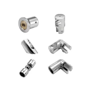
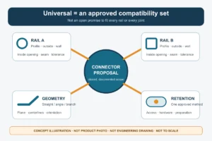
Square top rail components are selected around a chosen rail section and route. The purchasing task is to match the rail profile and wall condition with the straight joints, corners, ends and support interfaces shown on the project drawing. This page does not treat “components” as one fixed kit or imply that every combination is available.
Discuss square top rail components on WhatsApp
Freeze the rail section first
Give the outside width and height, wall thickness, inside opening, internal seam or corner radius and the required external corner appearance. These fields determine whether an internal sleeve, corner or end part can enter the rail and sit without a visible step. For a slotted or infill-receiving rail, also show the slot orientation and the infill or gasket interface.
If material and finish are important, state the requested exposure and appearance. The proposal should identify the actual proposed material, finish direction and matching method; the visible color or polish of a reference image is not a material certificate.
Use a component family, not a presumed kit
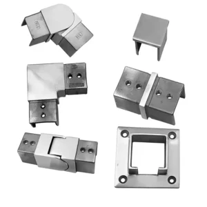
Straight joints
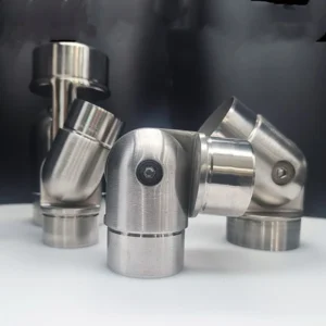
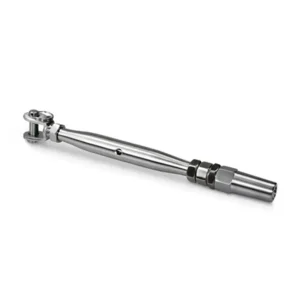
State the joint location, sleeve engagement on both sides, retention method and acceptable seam. Check that internal seams and wall variation do not block the sleeve. If the joint must accommodate movement, specify that requirement separately rather than assuming a standard connector sleeve will slide.
Corners and changes of direction
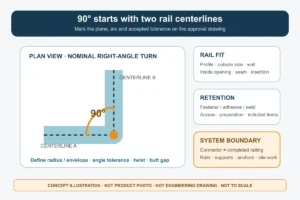
Distinguish horizontal plan corners from vertical stair or ramp changes. Provide the required inside or outside angle, rail orientation and whether the corner is a formed piece, a connector between cut rails or a fabricated joint. A part described only as a “90-degree corner” may still be wrong if its plane, outside radius or mating profile differs.
Ends and returns
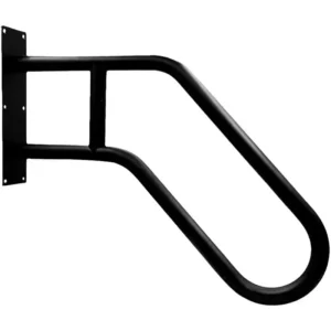
Mark every open end, wall termination and return. The choice between an end cap, a return or a wall interface changes the fixing and visible finish. Ask the proposal to identify whether the end part is decorative, mechanically retained or part of a larger termination detail.
Post, bracket and infill interfaces
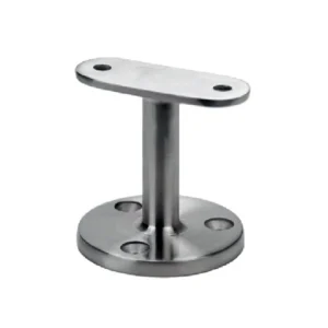
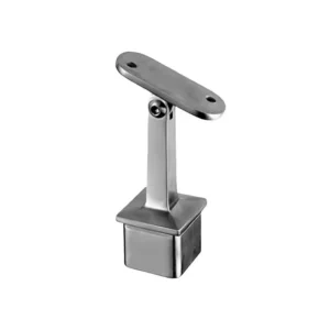
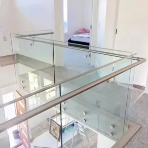
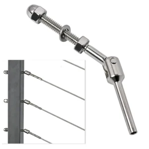
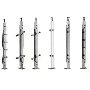
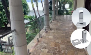
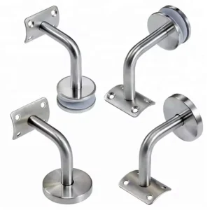
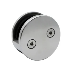
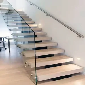
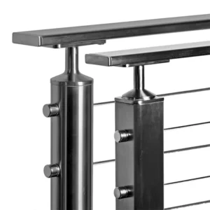
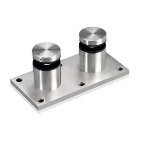
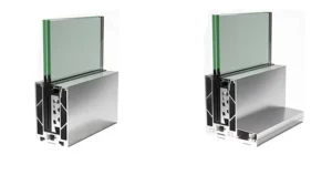
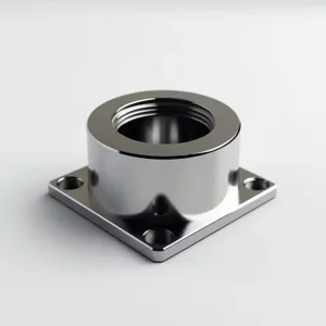
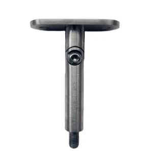
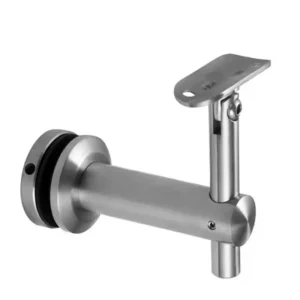
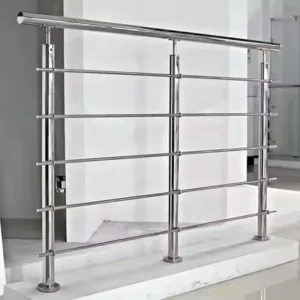
Show how the square rail is supported: on a post-top bracket, at a wall, over glass or another infill, or through a project-specific connector. Include the mating face, hole pattern, fastener access and rail orientation. A connector that fits the rail does not automatically fit the post, bracket or infill detail.

Make the quotation reveal the proposed scope
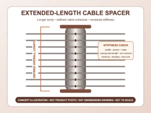
Ask for a line-by-line schedule rather than a generic “complete set.” Each line should name the proposed rail section, straight connector, corner type, end part, support interface, retention method, finish, quantity basis and any included fasteners or bonding materials. It should also identify field cutting, drilling, welding, sealants, infill, posts, anchors and installation work that are excluded unless specifically offered.
The component schedule does not replace complete-system review. Rail capacity, joint capacity, post spacing, post and base connections, anchors, substrate, infill design and project compliance remain responsibilities of the approved railing assembly and project design.
Information that lets suppliers quote the same requirement
- A rail end view with outside dimensions, wall thickness and any slot or internal obstruction.
- A plan and elevation showing straight joints, horizontal corners, vertical changes, ends and returns.
- Post or bracket interface sketches, fastener access and any glass or other infill relationship.
- Requested material and visible finish, exposure description, estimated lengths and component quantities.
- The parts required for the first approval sample and the dimensions that remain preliminary.
You can begin with photos, a hand sketch and approximate quantities. The useful next result is a proposed component schedule and interface drawing that make every assumption visible before production.