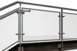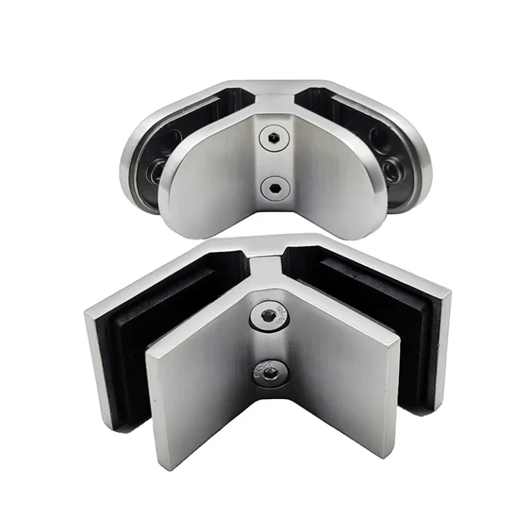
Heavy duty must be defined by the project’s design actions, glass assembly and complete load path—not by a larger-looking clamp. Send the panel layout, connection geometry, support details and required verification so a proposed clamp configuration can be compared on the same basis.
Discuss heavy duty glass clamps on WhatsApp
Translate heavy duty into a design brief
State what drives the request: panel size, guard or barrier use, crowd or service conditions, wind exposure, impact risk, connection spacing, a larger joint or a documentation requirement. The applicable project criteria and responsible designer should determine the actions and acceptance route. A “heavy duty” label, glass thickness or material grade alone cannot be converted into a safe working load.
Ask the proposal to identify the exact clamp assembly and the configuration for which any test data, calculations or certificates apply. Evidence for a different glass make-up, clamp spacing, anchor, substrate or joint arrangement should not be treated as evidence for the project assembly.
Choose the junction before the body
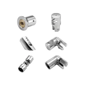
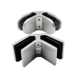
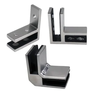
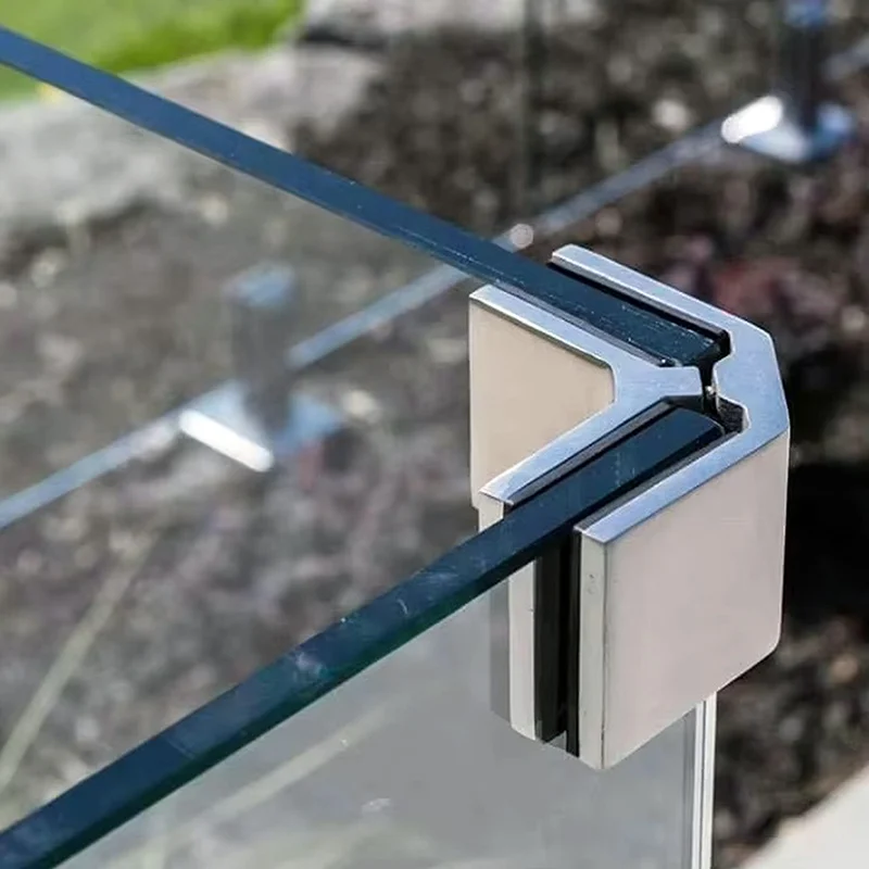
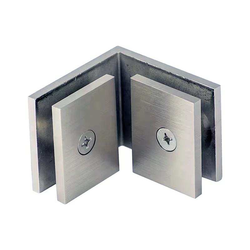
The visible product family includes broad glass-to-glass corner forms. A project may instead need an inline joint, a return angle, glass-to-post or glass-to-wall connection. Issue the angle, panel gap, face orientation and required sight line for every location. A fixed corner body should not be forced into an adjustable-angle requirement, and a glass receiver should not be treated as a mounting plate.
Coordinate glass, holes and retention as one detail
Provide monolithic or laminated construction, nominal build-up and tolerance, interlayer where relevant, edge finish and project-required heat treatment. Do not release glass from a catalogue photo. Confirm the proposed hole or notch pattern, edge distances and the relation to the connector centre on an approved drawing.
The proposal should distinguish:
- inlays or gaskets that match the stated glass build-up and separate the glass from the clamp body;
- glass-contact screws that close the clamp according to the approved installation procedure;
- locating or anti-slip parts used when the selected system requires positive positioning;
- joint or mounting fasteners that transfer actions to the adjacent connector or support;
- building anchors and backing that remain outside the clamp unless specifically listed.
For laminated glass, the responsible system designer must define the anti-slip and post-breakage strategy. A wider contact face does not by itself prove that the glass will be retained after breakage.
Support and anchorage remain part of the load path
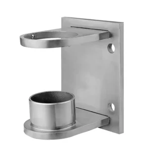
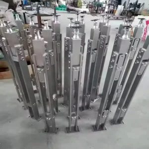
For glass-to-post or glass-to-wall use, issue the support material, profile, dimensions, thickness, backing and fastener access. For glass-to-glass joints, show how each panel is supported elsewhere and how the connector participates in alignment or load transfer. The clamp should not be asked to compensate for an undefined post, base plate, anchor or weak substrate.
The approved system detail should assign responsibility for clamp spacing, support stiffness, anchors, substrate checks, installation procedure and inspection. That boundary should also appear in the quotation so component supply is not mistaken for complete-system design.
Specify environment, grade and finish without overpromising
State indoor/outdoor use, coastal or de-icing exposure, pool or industrial chemicals, cleaning regime and desired appearance. If 304, 316 or another grade is required, ask the quote to identify the proposed material for the clamp bodies and exposed fasteners. “Heavy duty” does not mean that every material, finish or environmental version is available.
Material selection is not a substitute for drainage, crevice control, cleaning access and maintenance. Where traceability is required, request the relevant documents for the proposed supply rather than relying on a generic product-family statement.
Make heavy-duty offers comparable
| Control field | Buyer input | Quotation output |
|---|---|---|
| Duty basis | Project criteria, panel layout and connection actions from the responsible designer | Exact proposed configuration and evidence boundary |
| 玻璃 | Build-up, tolerance, edge and hole/notch drawing | Matched inlays and approved preparation |
| Junction | Inline/corner/return/support geometry and panel gap | Body form, angle and installed envelope |
| Retention | Required locating, anti-slip and post-breakage approach | Included pins/devices and fastener roles |
| System boundary | Component-only or coordinated hardware scope | Included parts, excluded glass/supports/anchors/engineering |
Information for a heavy duty clamp inquiry
- plan and elevation with panel dimensions, gaps and clamp locations;
- glass make-up, nominal thickness/tolerance, edge and hole/notch details;
- joint angles or support profiles, dimensions, thickness and backing access;
- project use, environmental exposure and applicable design criteria;
- required material grade, finish and verification documents;
- estimated quantity, destination and whether the request is component-only.
A preliminary sketch is enough to start. Before glass and installation are released, the proposed configuration should freeze the clamp body, inlays, retention method, fasteners, interfaces and system exclusions.
Heavy duty glass clamp questions
What load does a heavy duty clamp carry?
There is no responsible answer from the name alone. Capacity depends on the exact clamp, glass, spacing, joint, fasteners, supports, anchors and substrate, assessed against the project criteria.
Does thicker glass automatically need a heavy duty clamp?
No. Glass build-up is one selection field. Panel dimensions, support layout, holes, inlays and the complete design actions must be considered together.
Does a 316 clamp make the assembly suitable for marine use?
No. Other fasteners, surface condition, crevices, drainage, cleaning and surrounding supports also affect the environmental specification.
Can heavy duty clamps be bought as individual components?
Yes. Clearly identify a component-only request. The offer should list clamp bodies, inlays, screws, pins or caps and exclusions so system design is not implied.
What evidence should be requested?
Request evidence tied to the proposed configuration and the project’s acceptance route. Generic certificates or results for a different assembly should not be treated as proof for the completed project.