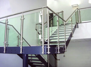
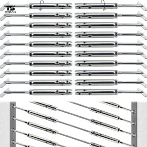
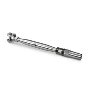
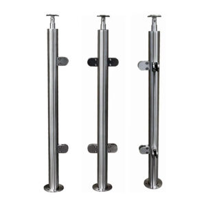
Choosing the wrong mounting method for cable railing hardware rarely reveals itself at purchase. It surfaces during framing inspection, when someone discovers the substrate behind a finished surface can’t document the load capacity needed to keep the cable run straight under sustained tension. By that point, waterproofing membranes are closed, blocking is inaccessible, and the only alternatives are callback work or accepting a surface attachment that hasn’t been verified for the force path it’s actually carrying. The judgment that prevents this isn’t about hardware price or profile preference—it’s about confirming substrate condition, hole geometry, and anchorage documentation before framing access closes.
Load Paths Created by Each Mounting Method
How a cable’s tension reaches the post—and how the post transfers it to the structure—differs fundamentally between through-post and surface-mount configurations, and the consequences of that difference extend beyond the fitting itself.
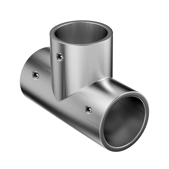
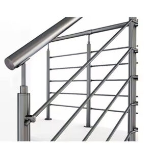
In a through-post layout, the cable enters and exits the post through aligned holes, and the post section carries the horizontal tension directly. There are no intermediate fittings absorbing or redirecting that force; the post material itself is the primary load-transfer element. This produces a mechanically clean path: tension runs from termination hardware through the post wall and continues to the next post without a change in load-bearing component. The load path’s integrity depends on hole alignment, post material, and post anchorage—not on how well a fitting grips an external surface.
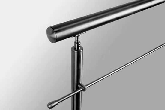
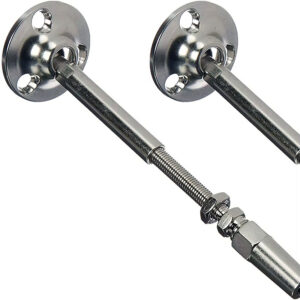
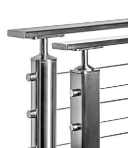
Surface-mount hardware creates a different arrangement. The cable terminates at or passes through a fitting attached to the face of a post, meaning the fastener connection between the fitting and the post surface enters the load path. Whether that introduces meaningful variability depends entirely on how the fitting and fastener system are specified and assembled. The performance of the full assembly—post, fitting, fasteners, and any intermediate hardware—is what determines load-path reliability, not the category of mounting alone. Treating surface-mount hardware as inherently weaker than through-post misframes the comparison; an underdocumented through-post installation with misaligned holes or inadequate post section can perform worse than a properly verified surface attachment.
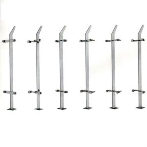
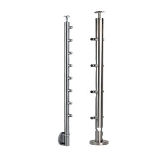
One manufacturer-specific example illustrates how these categories can converge: in the A-5 post configuration, the cable passes directly through 5/16″ holes without requiring any intermediate fittings, creating a continuous through-post path within what is otherwise a surface-mount post family. Other configurations in the same line use 1/2″ holes and require tension kits, insert sleeves, or inside mount kits, placing additional hardware in the tension path.
| Configuratie | Gatgrootte | Required Hardware | Load Path Characteristic |
|---|---|---|---|
| A-5 | 5/16″ | None – cable passes directly through post | Continuous through-post path; no intermediate fittings |
| A, A-2, C, D, I | 1/2″ | Tension kits, steel insert sleeves, or inside post mount kits | Hardware placed in the tension path; alignment depends on fitting assembly |
The A-5 configuration’s through-post characteristic is a design feature of that specific post, not a property shared across surface-mount systems generally. For the 1/2″ hole configurations, load-path performance depends on the full assembly integrity, including fitting seating, insert sleeve condition, and post anchorage—not on hole size alone.
Hole Alignment and Post Section Requirements
Hole alignment in through-post installations is a planning criterion, not an afterthought. When cables pass through a post wall, any deviation between entry and exit hole positions introduces a lateral force component that the post section wasn’t intended to carry. For straight runs, this is largely a fabrication quality issue—holes drilled or punched off-axis at the shop or on-site create a bend in the cable path that loads the post edge rather than transferring force cleanly through the section. At stair angles, the alignment problem becomes a geometry problem: entry angle, exit angle, and hole position must account for the cable’s actual travel path, not just the post face orientation.
Post section adequacy under cable loads is a separate concern from hole placement. As tension accumulates across a cable run—particularly at end posts and corner posts where the cable terminates or changes direction—the post must resist pull-out and lateral bending without local distortion around the hole. ASTM E894 provides a testing framework for assessing post anchorage under design loads, and its criteria are relevant when evaluating whether a given post section can carry the expected cable forces without deforming at the hole perimeter. The standard doesn’t prescribe specific hole alignment tolerances, but the load-path logic it supports implies that misalignment concentrates stress at the hole edge in a way that reduces effective section performance.
The practical planning consequence is that hole layout should be finalized against the manufacturer’s installation guide before posts are fabricated or ordered, not adjusted in the field. Field-drilled corrections to misaligned holes in steel posts are difficult to execute accurately and can reduce the effective section area if the correction hole overlaps the original. For aluminum posts, the material’s lower stiffness makes this margin smaller still.
Retrofit Access Versus Structural Continuity
Through-post configurations require drilling or punching holes through post material, which means the post must be accessible, removable, or at minimum drillable in place. In new construction, this is a scheduling decision. In retrofit work—adding cable railing to an existing stair, replacing a wood baluster system on a deck, or running cable along a finished masonry wall—the through-post option may be physically unavailable. The post may be fixed, the existing structure may not accept a drilled section, or the replacement post may need to be surface-mounted to avoid disturbing the substrate.
This is where surface-mount hardware becomes the structurally appropriate choice, not a compromise one. The engineering trade-off isn’t about force-path elegance; it’s about whether the attachment substrate and fastener path can be documented to carry the cable load reliably. ASCE/SEI 7-22’s load-path continuity concepts—the principle that lateral forces should transfer through connected elements without interruption—offer a useful analogy here. A surface attachment that interrupts the direct post-to-structure path with underdocumented fasteners creates a weak link in the same way an interrupted structural load path does. The question isn’t which method is superior in the abstract; it’s whether the specific retrofit conditions allow the surface attachment to perform equivalently.
The mistake pattern in retrofit projects is deferring the substrate check until the hardware is already specified or ordered. If the existing structure uses hollow section steel posts, thin-wall aluminum, or wood members with unknown blocking, the fastener path for surface hardware may not support the required pull-out resistance. Discovering this after hardware arrives pushes the project toward either a structural modification—opening the substrate, adding blocking, re-closing—or accepting an installation that can’t be verified for sustained cable tension.
For angled transitions and stair-to-landing intersections, surface-mount hardware often offers a practical geometry advantage: fittings can be positioned on a post face at the required angle without requiring the post section to accept a compound hole. This is a real installation benefit, but it doesn’t substitute for backing verification. The geometry advantage and the structural verification are separate checks.
Waterproofing and Backing Coordination Risks
Surface-mount hardware penetrates a finished surface to reach its fasteners. On wood decks, this creates potential water ingress paths at every fastener location. On concrete or masonry, anchor embedment depth and edge distance become variables that affect pull-out capacity. On framed walls with exterior cladding, the fastener path must pass through finish material and reach structural blocking—and if that blocking wasn’t specified and confirmed during framing, there may be nothing structural to reach.
The failure mode isn’t usually catastrophic and immediate. It develops over time: cyclical cable tension causes small movements at the surface fitting; water enters the fastener penetration; the substrate softens or corrodes; the fitting begins to rotate or loosen. By the time the misalignment is visible in the cable run, the backing condition that caused it may require significant remediation to fix. This sequence is avoidable, but it requires waterproofing and backing coordination to happen before framing is closed—not after hardware is selected.
The conditions that raise risk are identifiable. Fasteners placed in cantilevered deck framing without confirmed blocking carry higher pull-out risk than those placed at a ledger or post base. Membrane-over-substrate assemblies where the waterproofing layer must be penetrated require flashing or sealant coordination; if that detail isn’t specified, the penetration is an uncontrolled water path. Wood substrates in wet-exposure conditions without confirmed species, density, and blocking orientation introduce variability in fastener holding values that manufacturer installation guides typically assume have been verified.
The coordination implication is that the person selecting the hardware mounting method needs to know the substrate condition before making the choice—not at the same time as hardware pricing. On projects where backing installation is a separate trade scope, that confirmation requires an explicit RFI or design note, not an assumption that blocking will be present.
Evidence Needed to Approve a Surface Attachment
Approving a surface attachment for cable railing is not a hardware decision; it’s an anchorage documentation decision. The fitting itself can be correctly specified and properly assembled and still fail to perform if the surface it’s attached to can’t transfer the cable load to the structure.
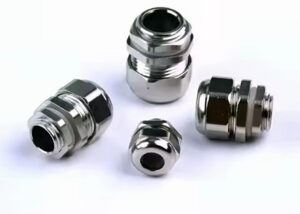
ASTM E894 addresses permanent metal railing anchorage testing and provides a reference framework for what constitutes adequate evidence of post attachment performance under design loads. The standard establishes minimum load thresholds for anchorage testing, not step-by-step installation instructions. Citing a manufacturer’s installation guide as equivalent evidence doesn’t satisfy what ASTM E894 requires: the guide may confirm proper assembly sequence, but it doesn’t substitute for anchorage performance data under the actual loading conditions of the installation. For kabelhardware voor opbouwmontage in engineered or permitted installations, the distinction matters—what the manufacturer specifies and what the anchorage testing framework requires are separate documentation items.
The approval threshold, practically, involves three verifiable conditions. First, the substrate must be identified by material, thickness, and backing presence, with fastener pull-out values available for that substrate under the expected load. Second, the fastener count, spacing, and embedment depth must be confirmed against the load calculation for that post position—end posts and corner posts carry different accumulated tension than intermediate posts and require separate review. Third, if the installation is in a wet-exposure or exterior location, the penetration sealing detail must be specified and inspected before it’s covered.
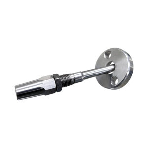
Projects that skip any of these checks before approval often treat the hardware product itself as the compliance item, which it isn’t. The through post cable fittings used in a through-post layout carry their own installation requirements—aligned holes, adequate post section—but the structural accountability is distributed differently. In a surface attachment, the fastener-to-substrate interface is the primary variable, and it’s the one most likely to be underdocumented if the review process doesn’t explicitly require it. For a broader comparison of how installation method affects the rest of the railing system, the surface mount vs. side mount cable railing overview covers additional method-to-project matching criteria.
The mounting method comparison in cable railing installations resolves to a substrate verification problem more often than a hardware selection problem. Through-post layouts distribute the load-path accountability across hole geometry, post section, and post anchorage—variables that are plannable during design and fabrication. Surface attachments shift a significant share of that accountability to the fastener-to-substrate interface, which requires its own documentation and is easiest to verify before framing is closed and backing access is lost.
Before specifying either method, confirm the post material and section against the manufacturer’s hole and load requirements, identify the substrate condition and backing presence at every post location, and determine whether the installation is in a wet-exposure context that requires a penetration sealing detail. Those checks should precede hardware pricing, not follow it. When they do, the choice between mounting methods becomes a structural fit decision rather than a callback waiting to happen.
Veelgestelde vragen
Q: What if my existing steel posts are too thin or cannot be drilled for through‑post hardware?
A: When the post section cannot accept a drilled hole without risk of local distortion or loss of structural capacity, surface‑mount hardware becomes the only practical mounting method. Thin‑wall steel, lightweight aluminium, or pre‑finished posts that cannot be field‑drilled require fittings that attach to the post face with documented fasteners. For those conditions, a verified surface‑mount solution avoids the risk of weakening the post itself, provided the fastener path and substrate are confirmed. For surface‑mount options designed to handle these constraints, see Esang’s kabelhardware voor opbouwmontage.
Q: What is the most time‑sensitive verification to complete before framing is closed off?
A: Confirm the presence, location, and material of blocking at every post position, because once drywall, sheathing, or deck boards are installed the fastener path can no longer be inspected or remediated without demolition. Schedule a pre‑close walk‑through with the framing contractor to photograph blocking and verify substrate thickness. This step locks in the data that surface‑mount approval depends on, so it must happen before hardware is even ordered.
Q: At what cable tension or span length does through‑post hardware start to risk deforming the post?
A: There is no universal tension threshold—the risk depends on post material, wall thickness, hole quality, and whether the post serves as an end, corner, or intermediate support. The article highlights that accumulated tension at end and corner posts is highest, and any hole misalignment concentrates stress at the hole edge. Manufacturer load tables for through‑post fittings usually specify the minimum post section and maximum run tension; without those values confirmed, the installation should be treated as unverified. ASTM E894 provides a testing framework but does not set prescriptive design limits.
Q: Once waterproofing and backing coordination are accounted for, is surface‑mount hardware actually the cheaper option?
A: Vaak niet. Bij opbouwmontage zijn de aanschafkosten voor de bevestigingsmaterialen in eerste instantie lager, maar het gelijktijdige werk van het controleren van de ondergronden, het aanbrengen van verstevigingsblokken en het ontwerpen van details voor het afdichten van doorvoeren maakt dit verschil vaak teniet of keert het voordeel zelfs om. In het artikel wordt opgemerkt dat de coördinatie van de waterdichting vaak bepalend is voor de gekozen methode, nog voordat de prijs van de bevestigingsmaterialen een rol speelt. Een echte kostenvergelijking moet deze voorbereidende stappen meenemen — de kostenbesparing van opbouwmontage is alleen reëel wanneer de ondergrond al voldoet aan de eisen voor het belastingspad zonder dat er extra herstelwerkzaamheden nodig zijn.
V: Is voor een klein terras bij een woonhuis waarvoor geen technische tekeningen nodig zijn, de volledige documentatie van de ondergrond en het testen volgens ASTM E894 echt noodzakelijk?
A: Formele verankeringstests volgens ASTM E894 worden zelden door de bouwvoorschriften voorgeschreven voor een terras bij een eengezinswoning, maar een beperkte controle van de toestand van de ondergrond en de houdkrachtwaarden van de bevestigingsmiddelen blijft essentieel om geleidelijke losraking te voorkomen. U kunt vertrouwen op de installatierichtlijnen van de fabrikant en een conservatieve afstand tussen de bevestigingsmiddelen in plaats van tests door derden, maar u moet nog steeds controleren of de palen en de ondergrond de kabelbelastingen aankunnen. Het volledig overslaan van deze controle is wat een eenvoudig project verandert in een prestatieprobleem op de lange termijn.