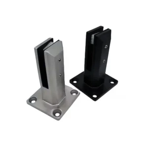
A surface mount handrail base plate shop drawing is ready for release when the post grid is keyed to verified site features, the plate and cover geometry are fully dimensioned, the structural substrate and the project-specified anchorage basis are named as separate references, and every open dimension or unresolved responsibility is visibly marked. A surface-mount base plate is the flat plate welded or formed at the foot of a railing post that sits on top of a finished or structural surface and transfers post loads into anchors set through holes in that plate. What changes the checklist from project to project is the substrate it lands on, the depth of floor build-up between the structural surface and the walking surface, and whether the anchorage basis has already been fixed by the project’s structural documents or is still open.
Anchor the Post Grid to Verified Datums and Site Features
Set the post grid against verified edges, joints, openings, and datum lines before releasing any base-plate hole pattern, because the hole pattern inherits every error in the setting-out it was dimensioned from. A grid drawn from a nominal slab edge rather than a surveyed one will still look correct on paper after the plates are drilled and the posts are welded, and the discrepancy only appears when the first row of anchors lands short of the edge distance the project assumed.
The site features that matter are the ones the plate physically competes with. Slab edges and nosings govern how much material sits outboard of the anchor group. Construction and movement joints govern where an anchor cannot be placed at all. Door openings, stair stringers, landings, and penetrations govern where a post must fall for the infill to work, which in turn pushes neighboring posts off an even division. Guard openings and infill spacing are also driven by this grid, so a post moved to clear a joint changes the clear dimension in two bays, not one.
Dimension the grid from named datum lines rather than running chains of post-to-post spacings. A chained string accumulates tolerance toward the last post, while a datum-referenced grid lets the installer set any post independently and lets the reviewer check any single location without adding up the whole run. Where a dimension is taken from an existing structure that has not been surveyed, show it as a field-verify dimension on the drawing rather than converting a site assumption into a fabricated hole center.
Show Plate Geometry, Hole Centers, Post Orientation, and Covers
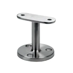
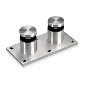
The base-plate detail has to carry five things in dimensioned form: plate profile and thickness, hole centers and hole diameters, post orientation relative to the plate and to the rail line, the weld or connection between post and plate, and the cover geometry that will sit over the finished assembly. Each of these is a fabrication instruction, and each one is also a coordination fact that another trade may need to read.
Post orientation is the item most often left implicit on a square plate. A square plate with a round post looks rotationally free, but the hole pattern is not: once the anchors are set in the slab, the plate can only drop on in the orientations the hole group allows. On a rectangular or slotted plate, orientation also decides which direction the slot takes up tolerance in, and that direction should face the dimension most likely to move on site. Show the orientation explicitly with a rail-line reference rather than leaving it to the installer to infer from the elevation.
Cover geometry belongs on the same detail as the plate. A cover flange, escutcheon, or shroud has an internal clearance, an outside diameter or footprint, and a height, and all three have to clear the plate, the anchor heads, any leveling nuts or shims, and the finished floor material. Showing the cover on a separate sheet from the plate is how a cover ends up unable to seat over an anchor head that stands proud.
These dimensions describe what gets fabricated and how the pieces fit together. They do not demonstrate that the connection can carry the applied guard loads. A plate can be dimensioned correctly, drawn to the right hole centers, and still be the wrong plate for the substrate and the design loads. Capacity is settled by the project’s structural design and the anchorage basis it specifies, not by the completeness of the fabrication detail.
Reference the Structural Substrate and Project-Specified Anchorage Basis
Name the structural substrate and the project-specified anchorage basis as two separate references on the drawing, because they answer two different questions and are usually fixed by different parties. The substrate is what the plate bears on and what the anchors engage: a structural slab of a stated thickness, a topping over metal deck, a precast element, a steel beam flange, or a supporting member below a non-structural topping. The anchorage basis is the specified anchor type, embedment, and installation conditions the project has adopted for that substrate.
The distinction matters because a surface-mount plate sitting on a floor tells you nothing about what is under the floor. A plate set on 50 mm of mortar bed over a structural slab, a plate set on a thin topping over steel deck, and a plate set on a cantilevered slab edge all look identical in plan. They differ in effective embedment available, in edge distance measured from a real structural edge rather than a finish edge, and in whether the anchor engages structure at all. Where the drawing shows a plate on a floor without identifying what that floor is made of and how deep the structure sits beneath it, the reviewer has no way to check the detail.
Keep the anchor callout on the drawing as a reference to the project’s specification rather than a supplier selection. A fabricator supplying plates, posts, and covers can state hole diameter and hole pattern, because those are fabrication dimensions. Which anchor goes in the hole, how deep it goes, and what edge distance it needs is a project connection decision resting on the structural documents and the authority having jurisdiction. Where the project has not yet fixed that basis, show the hole as a diameter with the anchor type noted as by others and flag it, rather than filling the callout with a plausible product name.
Cantilevered and edge conditions deserve a specific note. Where posts sit near a slab edge, the governing variable is the distance from the anchor group to the free edge of the structural element, measured from the structure and not from the finish. That dimension should appear on the drawing as a dimension, not as a visual impression in a section.
Separate Connection Design Inputs From Supplier Fabrication Scope
| Information or reference | Useful shop-drawing role | Te behouden grens |
|---|---|---|
| Plate profile, hole centers, post orientation, weld location, and cover geometry | Defines the base-plate fabrication and coordination detail to show | These dimensions do not establish connection capacity |
| Structural substrate | Identifies the support condition referenced by the drawing | Naming the substrate alone does not establish connection capacity |
| Project-specified anchorage basis | Records the project basis separately from the base-plate detail | The supplier’s base-plate scope does not replace project-specific connection decisions |
| UFGS 05 52 00 Metalen balustrades | Provides an example specification and submittal structure | Het is geen universele code of een productvereiste van ESANG |
| ASTM E985-24 | Provides a reference covering permanent metal railing systems and rails for building applications | It does not resolve specific field conditions; project designers, specification writers, and code authorities retain field-specific responsibility |
A shop drawing is proof of what will be fabricated and how the parts assemble; it is not proof that the connection has adequate capacity. Treating the two as the same thing is how an approved submittal becomes the only record anyone can point to when the anchorage is questioned later.
The practical boundary runs along who owns each piece of information. Plate profile, hole centers, post orientation, weld location, and cover geometry are supplier fabrication scope: the supplier can produce them, dimension them, and be held to them. Substrate identification and the anchorage basis come from the project’s structural and architectural documents. When a reviewer stamps the shop drawing, they are approving the fabrication detail against those project inputs, which means the inputs have to be visible on the same sheet for the review to mean anything.
Reference documents sit on a third line again. UFGS 05 52 00 Metalen balustrades is a federal guide specification for metal railings that is written to be edited for project-specific requirements, so it is useful as an example of how a railing specification and its submittal requirements can be structured, not as a code that applies to a given project by default and not as a statement of what any particular product provides. ASTM E985-24 covers permanent metal railing systems and rails for building applications and gives a common reference point for discussing those systems, but it does not resolve the specific field conditions on a project; the project designers, specification writers, and code authorities keep responsibility for those. Citing either document on a drawing is a reference, not a substitute for the project’s own connection decision.
The consequence for the drawing is simple. Where a fabrication dimension is shown, it should be owned and signed off by the supplier. Where a connection input is shown, it should be labeled as taken from a named project document or marked as outstanding. A drawing that mixes the two without distinction invites each party to assume the other has resolved the anchorage.
Coordinate Leveling, Floor Build-Up, Tolerances, and Installation Access
| Coordination item | What the drawing should make visible | Review decision |
|---|---|---|
| Leveling space | The space allowed for leveling at the base plate | Confirm it is coordinated, or mark the dimension as open before fabrication |
| Finished-floor build-up | The relationship between the base plate, cover, and finished floor | Confirm the build-up is represented before reviewing cover fit |
| Cover fit | The cover geometry in relation to the plate and finished floor | Confirm the cover can be reviewed against the shown interfaces |
| Tolerances | Where setting and interface tolerances are accommodated | Do not leave tolerance to an unreviewed field adjustment |
| Toegang tot de installatie | The access needed to install the shown base-plate arrangement | Confirm access is coordinated, or mark it unresolved before fabrication |
Leveling space, finished-floor build-up, cover fit, tolerance allocation, and installation access all meet at the base plate, and all five need to be visible on the drawing so that tolerance is designed rather than absorbed by whoever happens to be on site when the post does not sit flat.
Leveling is the first of these because it changes the geometry of everything above it. A plate set directly on the floor has no room to correct a slab that falls away or a post that must stand plumb against a sloped surface. A plate set on leveling nuts, shims, or a grout bed gains that correction and in exchange raises the underside of the plate, which raises the required cover height and exposes anchor shank between the slab and the plate. Decide which arrangement the project uses and show the resulting stack height on the section, because a cover sized for a flush plate will not seat over a shimmed one.
Floor build-up is the second. The distance from the structural surface to the walking surface determines whether the plate is buried under the finish, sits on the finish, or sits on the structure with the finish closing around it. Each case changes the visible cover profile, the exposed fastener length, the water path at the plate edge on an exterior deck, and the sequence of work between the railing installer and the flooring trade. Draw the finish layers in the section rather than describing them in a note.
Tolerance should be allocated deliberately and shown. Slot direction, oversize holes, shim packs, and cover overlap are the places tolerance can live, and each has a limit beyond which the detail stops working: an oversize hole reduces bearing area, a tall shim pack adds bending in the anchor shank, and cover overlap has a finite reach before the plate edge shows. Naming where the tolerance goes on the drawing is what keeps a 10 mm setting-out discrepancy from being solved by an undocumented field modification to the plate.
Installation access is the item that gets checked last and causes the most rework. Confirm that a drill and a torque wrench can reach every hole in the shown orientation, that a post close to a wall, a column return, or a stair stringer still leaves working room for the anchor heads, and that posts installed in sequence do not block access to the next base plate. Where a plate sits tight against an obstruction, either rotate the hole pattern so the blocked holes become accessible or move the post, and show that decision rather than leaving it to the installer.
Release the Drawing Only After Open Dimensions and Responsibilities Are Marked
| Release check | Evidence required on the revision set | Release decision |
|---|---|---|
| Post grid | Grid keyed to verified edges, joints, openings, and datum lines | Release only when the setting-out basis is shown |
| Base-plate detail | Plate profile, hole centers, post orientation, weld location, and cover geometry shown | Release only when the fabrication detail is complete |
| Connection references | Structural substrate and project-specified anchorage basis identified separately | Keep any unresolved reference or scope boundary marked |
| Installation interfaces | Leveling space, finished-floor build-up, cover fit, tolerances, and installation access coordinated | Keep any unresolved interface dimension marked |
| Open dimensions | Every unresolved dimension visibly identified | Do not release an unmarked open dimension for fabrication |
| Responsibility boundaries | Unresolved project and supplier responsibilities visibly identified | Do not release an unmarked responsibility boundary for fabrication |
Release the revision set for fabrication only once every unresolved dimension and every unresolved responsibility boundary is visibly marked on the drawing itself, not held in a review comment, an email, or a meeting note. An open dimension that is tracked somewhere other than the drawing becomes a closed dimension the moment the drawing reaches the shop floor.
Marking means the drawing shows the condition in a way a fabricator and an installer both read the same way: a field-verify flag on a dimension taken from an unsurveyed existing surface, a hold note on a hole pattern waiting for the structural anchorage basis, a by-others callout against an anchor type the supplier does not select, and a clouded revision mark on anything that changed since the last issue. The test is whether someone who was not in the review can tell, from the sheet alone, which dimensions are fixed and which are still moving.
The release decision itself is a project approval, and it belongs to the project’s approved submittal procedure and its designated approver rather than to the fabricator or the installer. Where a reviewer returns a drawing with an anchorage comment, the comment closes when the project document that settles it is named on the drawing, not when the dimension is simply filled in to allow fabrication to start.
For the discussion that gets a drawing to this point, have the setting-out basis and the substrate information in hand: the surveyed edges, joints, openings, and datum lines the post grid will be keyed to; the structural makeup beneath each run, including finish build-up depths and any topping over deck; the project specification section governing railings and the structural document that fixes the anchorage basis; the guard loads and post spacing the design is based on; and the exposure and specified stainless grade and finish, since coastal conditions affect the plate, cover, and fastener selection together rather than one at a time. With those in front of both parties, the base-plate detail can be dimensioned once and marked honestly where it is still open.
Veelgestelde vragen
V: What should be confirmed before the base-plate hole pattern is released?
A: Confirm that the post grid is tied to verified datum lines, edges, joints, and openings. If any setting-out dimension remains unverified, identify it as open on the revision set instead of allowing the fabricator or installer to infer it.
V: Does a fully dimensioned base plate prove that the handrail connection has adequate capacity?
A: No. Plate profile, hole centers, post orientation, weld location, and cover geometry define fabrication and coordination information, but they do not establish connection capacity. The drawing should identify the structural substrate and the project-specified anchorage basis separately so the project-specific connection decision remains visible.
V: What should the reviewer do when the finished-floor build-up is still changing?
A: Keep the affected base-plate, leveling, and cover interfaces marked as unresolved until the build-up can be coordinated. The review should show where tolerance is intended to be accommodated and whether installation access remains workable, rather than leaving the issue to an unreviewed field adjustment.
V: How should a different substrate found on site be handled against the approved drawing?
A: Treat it as a change to a connection input, not as a minor drafting difference. Reconcile the actual substrate with the project-specified anchorage basis and record the resulting responsibility or drawing update before relying on the original base-plate detail for installation.
V: Can UFGS 05 52 00 or ASTM E985-24 be used as the sole approval basis for the shop drawing?
A: No. UFGS 05 52 00 can inform specification and submittal structure, while ASTM E985-24 covers permanent metal railing systems and rails for building applications. Neither reference resolves the project’s field conditions, so the applicable project requirements, substrate, anchorage basis, and responsible decision makers still need to be identified.