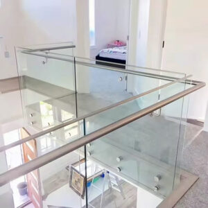
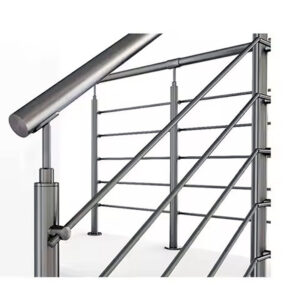
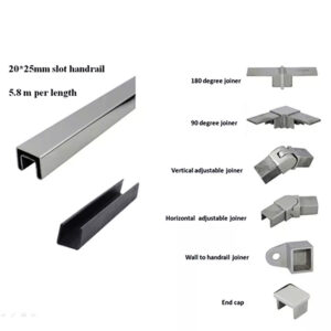
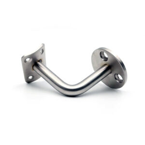
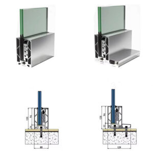
Gaas opvulpanelen only appear straightforward until someone has to fit one between a post that has already been fabricated and a rail profile that has already been ordered. Before that panel goes into production, the project team has to decide how it engages the posts, how it relates to the top and bottom rails, and whether every one of those interfaces is documented the same way across drawings, schedules, and shop details. Getting this sequence wrong does not usually show up until fabrication, when a mismatch is far more expensive to fix than it would have been to catch on paper.
Treat the Panel as Part of a Railing Assembly
A wire mesh infill panel fills the opening between posts and between the top and bottom rails. It does not stand as an independent structural element, and its presence in a railing run does not by itself establish how the assembly as a whole will perform. The panel’s dimensions, edge condition, and fixing method only make sense in relation to the posts and rails that surround it, because those adjoining members define the opening the panel must fill and the connection points it must reach.
This matters because a panel can be dimensionally correct and still be the wrong panel for the assembly if the post spacing, rail profile, or connection type it was designed against does not match what is actually specified for that run. Where the post-to-post spacing varies along a railing line, or where different rail profiles are used at different locations, a single “standard” panel detail will not carry through the entire project without adjustment. The panel’s role is to close a defined opening under a defined fixing method; when either the opening or the fixing method changes, the panel has to change with it.
This is also why panel selection cannot substitute for review of the whole railing structure. A panel that fits a given post-and-rail condition today may not fit if the post shape, spacing, or rail profile is revised later in design development. Confirming panel geometry before those upstream elements are locked introduces a risk that fabrication proceeds against a condition that has since changed. The coordination discipline here is to treat the panel geometry as a downstream output of the posts and rails, not as an independent input that the rest of the assembly is expected to accommodate.
For this reason, mesh panel coordination is best approached through the wire mesh infill panel documentation together with the post and rail interfaces it depends on, rather than as a standalone product decision made in isolation from the rest of the railing system.
Coordinate the Post Interface
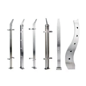
The post is one of the two structural references the panel must key into, and post conditions vary in ways that change what information needs to be confirmed before a panel can be detailed. An intermediate post along a straight run presents a different coordination problem than a terminal post at the end of a run, and a corner post presents a different problem again, because each condition changes the panel’s edge treatment and the angle at which it meets the adjoining structure.
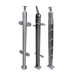
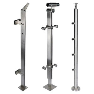
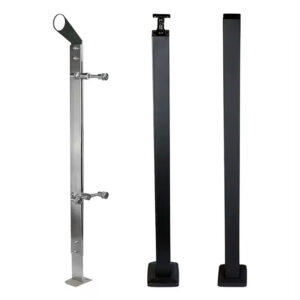
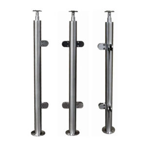
Post shape and spacing set the outer dimension of the opening the panel fills, but shape also affects which connection methods are physically possible. A round post accepts a different bracket or clamp geometry than a square or rectangular post, and a post with prepared holes for mechanical fixing implies a different panel edge detail than a post intended for welded tabs. Where the post has not yet been detailed for a specific connection method, the panel cannot be finalized either, because the panel’s edge condition is a direct response to how it attaches to the post.
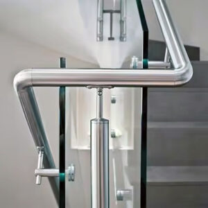
Corner and terminal conditions add a further layer, since the panel’s termination at these points depends on handedness and the angle between adjoining runs, not only on the post’s cross-sectional shape. A panel edge detail that works cleanly at a straight intermediate post may not resolve at a corner without a distinct detail for that location.
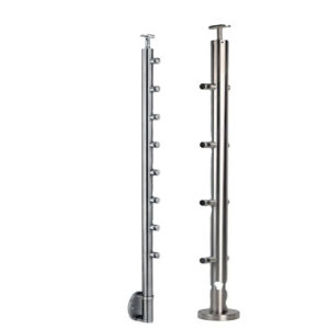
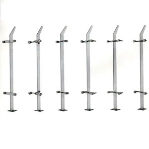
The practical risk in this interface is not the individual pieces of information but whether the field condition and the fabrication drawing use the same reference points. If the post spacing recorded in the field differs from the spacing used to generate the panel schedule, or if the fabrication reference assumes a connection type that was later changed, the mismatch will not surface until the parts arrive on site. Reviewing stainless steel posts alongside the panel schedule, rather than treating the post as a fixed background condition, is what keeps the datum consistent between the two.
| Post condition | Information to coordinate |
|---|---|
| Intermediate post | Shape, spacing, and panel connection locations |
| Terminal post | End condition and panel termination detail |
| Corner post | Adjacent-run angle, handedness, and fixing faces |
| Prepared connection | Holes, tabs, brackets, clamps, sleeves, or specified alternative |
Coordinate Top- and Bottom-Rail Interfaces
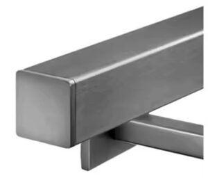
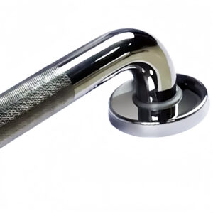
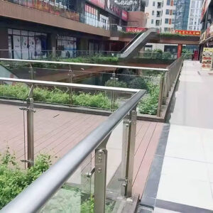
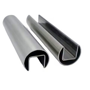
Where the post interface sets the panel’s side conditions, the top and bottom rails set its upper and lower conditions, and the two rails do not necessarily behave the same way. A top rail may serve only as a cap or handhold, with the panel supported entirely from the posts, or it may be detailed to receive and support the panel edge directly. A bottom rail, similarly, may simply bound the lower edge of the opening, or it may include a sleeve or support detail that carries the panel. Which relationship applies changes what the panel edge needs to do at that boundary, and the wrong assumption at this stage produces a panel that has no way to engage the rail it was meant to meet.
This is also where alignment and gap questions arise, and here the governing rule is that only the project’s own specified criterion and datum apply. A gap between panel and rail, or an alignment tolerance for pattern continuity across panels, is a project-specific decision rather than a fixed industry default, because different rail profiles present different bounding faces and different visual and functional requirements for how the mesh should sit against them. Assuming a particular rail profile or a particular gap without confirming it against the project drawings risks fabricating panels to a standard that the actual rail does not support.
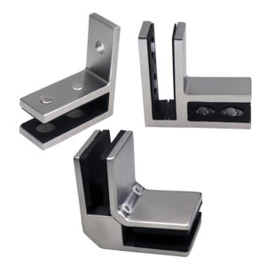
The fixing type and location at each rail follow the same logic as at the post: mechanical fixing, welded tabs, or another connection method each imply a different panel edge preparation, and the choice has to be confirmed rather than inferred from the panel’s general category. Manufacturer references such as Newark Wire Works, in describing wire mesh panels fastened mechanically, by welded tabs, or welded to rail or tube posts, illustrate that more than one connection approach exists for comparable panel types, and that the major panel dimensions have to be defined before any of those connection methods can be finalized. That illustrates the range of approaches in general; it does not establish which method applies to a given project’s rail and post combination, which remains a matter for the specific top rails and bottom rails detailed for that run.
Where the top rail supports the panel and the bottom rail does not, the panel’s structural engagement runs almost entirely through the upper edge, and the lower edge detail becomes a matter of appearance and closure rather than load transfer; where both rails support the panel, the edge condition at each has to be resolved with equal care, since either one being wrong compromises the fit of the whole panel rather than just one edge.
| Rail interface | Confirm from project documents |
|---|---|
| Profiel | Shape and bounding face |
| Support relationship | Whether and how the panel is rail-supported |
| Fixing | Type and location of connection |
| Panel edge | Frame/edge position relative to the rail |
| Alignment/gap | Only the project-specified criterion and datum |
Resolve Corners, Stairs, and Transitions
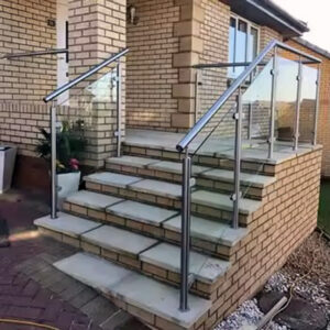
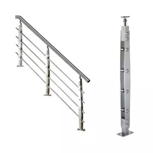
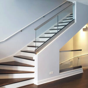
Straight runs on a level plane are the condition against which most panel details are first developed, and corners, stairs, and transitions are the conditions that break that assumption. A corner changes the angle between two adjoining panel runs and introduces a handedness question that a straight run does not have, since the post faces on either side of the corner are not parallel and the panel termination at each face has to resolve against the other. A stair run changes the panel’s frame orientation relative to the posts, because the panel follows the rake of the stair rather than sitting level, which affects how the top and bottom edges relate to their respective rails along a sloped rather than horizontal line.
A landing sits between these two conditions, since it returns to a level plane but has to connect cleanly to the raked panels on either side, and the transition from raked to level is itself a distinct geometric condition that a standard panel detail does not automatically resolve. Where a pattern or module in the mesh is meant to read continuously across a run, the transition point is also where that continuity is most likely to break, because the panel geometry changes at exactly the point where visual alignment matters most.
The practical consequence of these conditions is that a panel intended for a corner, a stair, or a landing cannot be treated as an instance of the same detail used for a straight, level run. Each of these locations is a non-repeating condition, and documenting it as though it were a repeating one is what produces a panel that does not fit when it reaches the field. This is the reasoning behind assigning unique panel marks and distinct details wherever the interface differs from the standard run: the mark is not a labeling convenience but a record that the geometry at that location has been worked out on its own terms rather than assumed from an adjacent condition. Where a project has multiple corners or stair-to-landing transitions that look similar but are not identical in angle or rake, each one still needs its own resolved detail rather than a shared one, because a resemblance in appearance does not confirm that the underlying geometry is the same.
| Bedrijfsomstandigheden | Coordination focus |
|---|---|
| Hoek | Post faces, run angle, panel termination, and handedness |
| Stair | Slope, frame orientation, post locations, and rail relationship |
| Landing | Level interface and connection to adjacent stair panels |
| Overgang | Change in geometry, pattern reference, and unique panel mark |
Close the Review Before Fabrication
Before fabrication proceeds, the coordination work done at the post, rail, and transition interfaces has to be checked against the full set of project documents rather than accepted piecemeal. This means confirming that plans, elevations, sections, the panel schedule, and the connection details all refer to the same panel by the same mark and the same revision, since a panel mark that has been updated in one document but not another is a direct path to a mismatch at fabrication. UFGS 05 52 00 Metalen balustrades, as a guide specification structure, calls for detailed fabrication drawings, member and connection information, and accurate angles to be established and reviewed before fabrication proceeds, along with a process for identifying and approving deviations; that structure describes a general coordination discipline for metal railing work and does not by itself confirm that a given project’s documents meet it.
Material and finish continuity belongs in this same review, separate from the geometric checks, because a panel that fits dimensionally can still be wrong if its material grade or finish does not match what the rest of the railing assembly specifies. Where a project has not yet resolved a finish sample or a material specification, that is a hold condition rather than a detail to be finalized during fabrication.
The review also has to separate what the supplier’s fabrication scope covers from what remains the responsibility of others on the project. A supplier fabricating panels to a confirmed geometry and connection detail is working within that fabrication scope; that scope does not extend to structural design, code review, or the installation and final acceptance of the assembly, and it does not confirm that a particular finish, size, or customization is available for every order unless that has been separately established. The project information the buyer supplies, such as the confirmed post and rail interfaces, material and finish requirements, and panel marks, is what a supplier uses to review and quote a matching set of components, but that review does not substitute for the project team’s own confirmation of structural adequacy and code compliance. Where drawings, schedule, and connection details are aligned and material and finish are resolved, the coordination record supports moving to fabrication; where any of these remain in conflict or unresolved, that is the condition to hold against until it is settled, and confirming this handoff before releasing panels for production is a separate and necessary decision from confirming the geometry itself.
| Review item | Proceed when | Hold for |
|---|---|---|
| Drawings and schedule | Same panel marks and revisions align | Conflicting identity or geometry |
| Verbindingen | Post and rail details match the panel fixing | Missing or contradictory interface |
| Materiaal/afwerking | Project requirement is clear | Unresolved specification or sample |
| Responsibilities | Supplier and project approvals are named | Engineering or acceptance scope is assumed |
Veelgestelde vragen
V: Can a panel be finalized if the post spacing is known but rail details are still open?
A: No, spacing defines only part of the opening. The panel also needs the top- and bottom-rail profiles, support relationship, edge position, and fixing locations. Coordinate these with the post shape and connection points using consistent datums and the project’s specified alignment or gaps.
V: What is different about a corner or terminal panel compared with an intermediate panel?
A: Its termination and receiving interfaces may differ. At corners, the adjacent-run angle, fixing faces, and handedness need to be shown; at terminals, the end connection and panel termination need definition. Use distinct marks and details where these conditions differ rather than apply a typical intermediate connection automatically.
V: Which drawing conflicts should be resolved before the panels go into fabrication?
A: Resolve mismatched panel marks or geometry between drawings and schedules, missing or contradictory post-and-rail connections, and open material or finish requirements. Cross-check plans, elevations, sections, connection details, supporting conditions, and deviations under matching revisions. Also name the supplier’s fabrication scope and the separate project reviews for engineering, code, installation, and final acceptance.