Selecting a bracket and ordering a rail before confirming what the wall is made of is the single fastest way to generate a rejected installation. The consequence is not abstract: a contractor who arrives on site with wood-screw hardware and discovers a concrete block wall faces remedial anchoring, schedule pressure, and a handover delay that could have been resolved at the specification stage. The decision that prevents it is substrate confirmation before bracket selection, not during installation. What follows gives you the specific dimensions, anchor logic, and ordering checks that change the outcome at each stage of the procurement and installation process.
Wall substrate checks before bracket selection
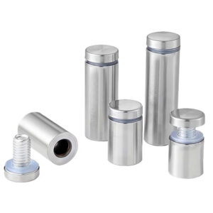
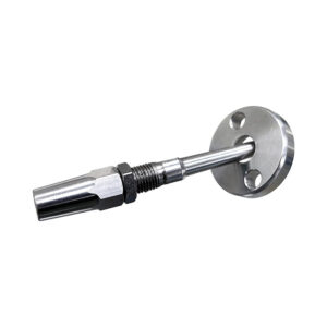
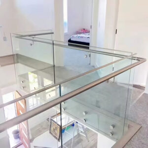
Wall condition is a decision gate, not a background detail — and product pages rarely treat it that way. A bracket shown in a polished finish photo carries no visible signal about whether its included hardware will work in your wall. The mismatch only becomes visible when the installer opens the box on site.
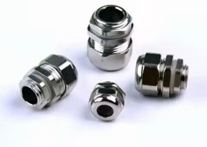
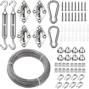
The anchor pairing that comes with a standard bracket kit follows the substrate: wood screws for timber stud framing, masonry anchors for concrete or block. These are not interchangeable. Wood screws driven into concrete without a pre-drilled anchor point will not develop meaningful pullout resistance, and masonry anchors set into hollow cavity framing are similarly unreliable. The substrate determines the fastener, and the fastener determines whether the installation holds under lateral load.
The operational difference between the two paths is also a tool difference. Timber framing requires a standard drill driver. Concrete or masonry installation requires a rotary hammer to produce a clean, correctly sized hole for the anchor to seat properly. If the installer brings only a standard drill, a masonry wall stops the job. That is a procurement and site-preparation failure, not a product failure — and it is avoidable if substrate type is confirmed before the kit ships.
| 基底类型 | Supplied Anchor/Fastener | Tool Required | Risk if Wrong Anchor Used |
|---|---|---|---|
| Wood stud | Wood screws | 标准电钻/起子机 | Installation failure or rework |
| Concrete/masonry | Masonry anchors | Rotary hammer | Installation failure or rework |
One practical implication the table does not resolve: mixed substrate runs are common in renovation projects where a stair wall transitions from a framed partition to a poured concrete section. In that case, the anchor selection changes mid-run, and both fastener types need to be on site before drilling begins. Confirming the full wall condition along the stair run — not just at one bracket location — is the check that prevents a mid-installation stop.
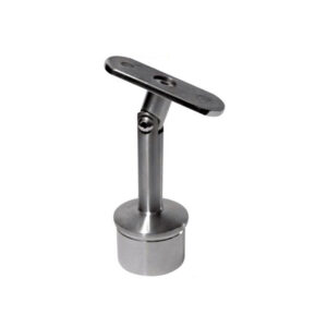
Projection and load path effects on bracket type
A bracket’s projection — the horizontal distance from the wall surface to the center of the rail — directly shapes how load transfers back into the anchorage point. A longer projection increases the lever arm on the fastener group, converting a horizontal grip load into a greater rotational moment at the wall face. This is why projection is a planning input, not just an aesthetic preference.
The standard bracket projects 3.5 inches from the wall to the rail centerline. That figure comes from the product specification and functions as a layout dimension: it tells you where the rail center will land relative to the finished wall surface. For load path purposes, it means the fastener cluster at the wall face is resisting both a direct shear component and a prying moment generated at that 3.5-inch offset. Anchorage behavior under combined loading — particularly where stud engagement is partial or substrate resistance is uncertain — is the kind of condition addressed by testing frameworks like ASTM E894-88, which covers anchorage performance of permanent metal railing systems under load. That standard does not specify the 3.5-inch figure, but it is the relevant reference for understanding why projection influences how anchor capacity needs to be evaluated.
The practical implication for bracket selection is this: if the wall condition is already marginal — a single stud available, hollow block, or unknown cavity fill — a higher-projection bracket amplifies the demand on that anchorage. A lower-projection bracket reduces it. Treating projection as a purely spatial variable while leaving anchor capacity as a site assumption is the error pattern. These two variables need to be evaluated together during bracket selection, not sequentially after the bracket has already been ordered.
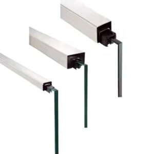
Tube size alignment with gripping and clearance requirements
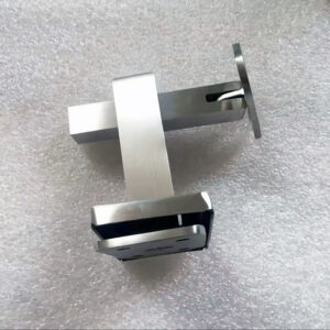
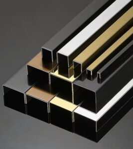
Rail-to-wall clearance is a gripping and safety criterion, not a comfort preference. The clearance band — a minimum of 1.5 inches and a maximum of 4.5 inches between the face of the handrail and the adjacent wall surface — defines whether a user’s hand can wrap the rail securely and move along its length without obstruction. A rail mounted too close to the wall restricts hand passage; one mounted too far out changes the loading geometry and ergonomic reach angle for users on the stair.
This range is a planning criterion that must be verified during layout, before installation proceeds. The 3.5-inch bracket projection to rail center means the rail face will sit slightly inward of that centerline depending on tube diameter. A standard 1.5-inch or 2-inch round tube produces a finished clearance that typically falls within the acceptable band when mounted to a flat wall using a standard bracket — but that calculation changes if the wall surface has been modified. Tile, cladding, thick plaster, or a wainscot cap applied after the original measurement was taken can reduce the effective clearance and push the installation outside the acceptable range without anyone realizing it until the rail is already set.
Tube diameter also affects graspability independent of clearance. A tube that is too large in diameter reduces the grip arc, particularly for smaller hands, while a tube that is too small can feel unstable under downward and lateral load. ANSI/NAAMM AMP 521-01 provides design guidance for pipe railing systems including graspability considerations, and it is the appropriate reference for cross-checking tube sizing decisions where project specifications require it. For standard residential and light commercial stair applications, confirming that the finished tube diameter aligns with expected user grip range — and that the clearance calculation reflects the actual finished wall surface, not a pre-cladding measurement — is the check that prevents a non-conforming installation after the rail is already in place.
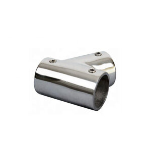
If you are selecting tube dimensions as part of a broader railing system specification, 不锈钢墙扶手 are available in configurations that allow clearance and graspability to be verified before commitment to a bracket type.
Anchor and backing conflicts installers catch before drilling
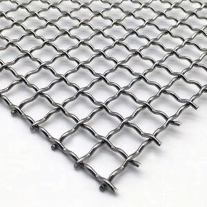
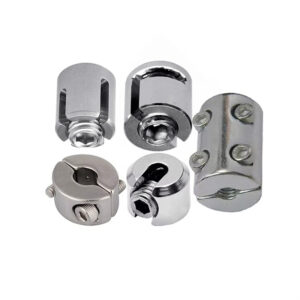
The stud engagement requirement has a specific failure shape. Of the four screws used to mount a standard bracket plate, at least two must engage a structural stud. If both stud-engaged screws are on one side of the plate and the other two land in drywall only, the plate rocks under load rather than transferring it evenly. That asymmetry increases the demand on the two anchored screws and creates a progressive loosening pattern that is not always visible from the rail surface until the bracket is already working loose.
The pre-drill check that catches this is straightforward: locate studs along the full stair run before marking bracket positions, confirm that spacing between brackets allows the minimum two-of-four engagement at each location, and identify in advance where stud spacing will not align with required bracket spacing. When no stud is accessible at a required bracket location, the path forward is not to proceed with drywall fasteners — it is to evaluate whether blocking can be added behind the wall surface, whether bracket spacing can be adjusted to reach the next stud, or whether the wall-mounted approach is viable at that run at all.
For deeper guidance on how bracket spacing and wall conditions interact across different stair configurations, stair handrail brackets: how installers prevent clearance and anchoring conflicts on real stair runs covers this in more detail.
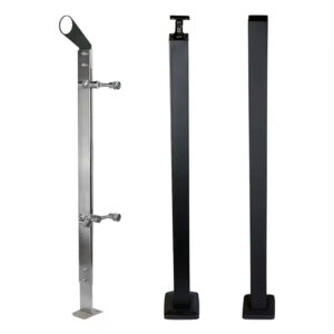
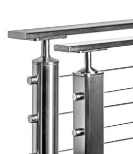
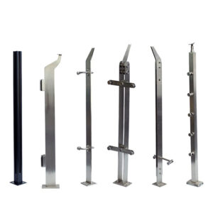
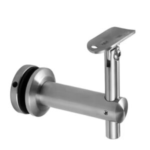
The trade-off between wall mounting and post mounting is often treated as a style decision, but it is more accurately a structural access decision. Wall mounting preserves stair-edge geometry and does not require floor penetrations, which matters on finished tile or hardwood floors. Post mounting sidesteps weak or inaccessible wall conditions but introduces floor core drilling and a structural review of the substrate beneath the floor finish. Neither option is inherently superior — the right choice depends on what the site can support. Making that determination before drilling begins is what separates a clean installation from a remedial one.
Purchase decision after bracket spacing and wall condition are verified
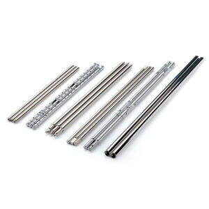
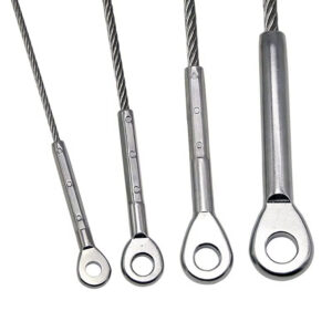
Length ordering is the last point in the procurement sequence where a small miscalculation creates a day-of-installation problem. The correct measurement for handrail length is not the stair run dimension read from a drawing — it is the nose-to-nose distance between the first and last step, plus 16 inches added for the total end-to-end length. That addition accounts for the handrail extending beyond the stair edges at both ends, which affects usability and often reflects guidance in applicable building codes or safety references for your jurisdiction. Ordering against the stair run dimension alone produces a rail that is consistently short, and that shortfall is not a field fix.
| Ordering Step | What to Do | 为何重要 |
|---|---|---|
| Measure stair run | Measure nose‑to‑nose step distance, then add 16 inches for total end‑to‑end handrail length | Ensures handrail extends properly beyond the stair edges |
| Check length against stock | If total length exceeds 10 ft, order multiple 10‑ft handrail lengths and splice hardware | Standard handrail sections are 10 ft; splices connect runs longer than one section |
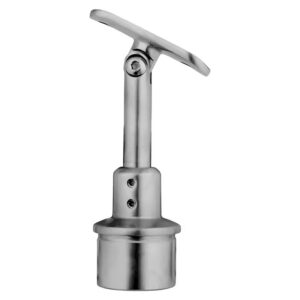
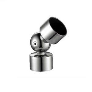
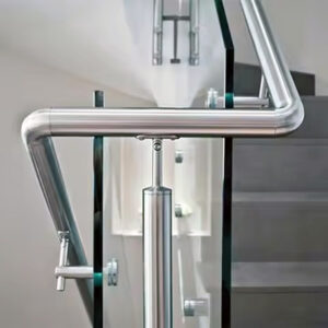
The 10-foot stock length creates a second ordering checkpoint. Stair runs that exceed 10 feet require multiple rail sections and splice hardware to connect them. Splice hardware is not always visible in a standard product listing and is easy to omit from the initial order. Discovering that it is missing on installation day means either a trip to source it or a stalled installation — both preventable if the total calculated length is checked against the 10-foot section limit before the order is placed. 可调节墙壁扶手支架 can accommodate angle variation across runs, which may also affect how splice points align with bracket positions when planning a multi-section installation.
Bracket spacing itself affects the order count in a less obvious way: spacing decisions made in response to stud locations can shift bracket positions, which can in turn shift where a splice falls within a run. Confirming that a splice does not land directly at a bracket location — where the two hardware elements compete for the same wall zone — is the kind of layout check that is difficult to reverse after fabrication.
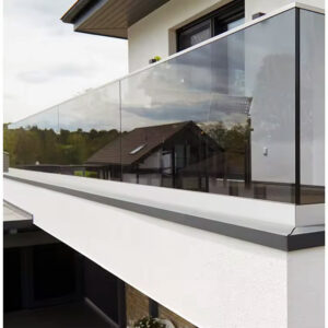
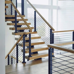
A wall-mounted stainless steel handrail is a viable and space-efficient solution for the majority of stair configurations, but it functions that way only after the substrate, anchor access, and clearance conditions have been confirmed — not assumed. The decisions that typically cause rework are made before the first bracket is placed: ordering against an unverified substrate, calculating length from a drawing rather than a nose-to-nose field measurement, and omitting splice hardware for runs that exceed a single section.
The most useful pre-purchase check is to treat substrate type, stud spacing, finished wall surface dimension, and total run length as four separate confirmed inputs — not as details to resolve during installation. Each one affects a different part of the order: fastener type, bracket selection, clearance calculation, and section count. When all four are resolved before the order is placed, the installation becomes a predictable sequence rather than a site problem.
常见问题
Q: What happens if the wall along the stair run is a mix of timber framing and concrete — do you need both anchor types on site?
A: Yes, both fastener types are required before drilling begins. A mixed-substrate run means anchor selection changes at the transition point, and arriving with only one fastener type will stop the job mid-installation. Confirm the full wall condition along the entire stair run — not just at a single bracket location — so the correct hardware is on hand before any holes are drilled.
Q: If stud spacing on site doesn’t align with the required bracket spacing, is wall mounting still viable?
A: Not automatically — this is a site decision, not a product fix. When stud locations cannot support the minimum two-of-four screw engagement at a required bracket position, the options are to add blocking behind the wall surface, adjust bracket spacing to reach the next available stud, or evaluate whether post mounting is the more structurally sound choice for that run. Proceeding with drywall fasteners at under-supported locations creates a progressive loosening failure that may not be visible until the bracket is already working loose.
Q: Does wall-mounted or post-mounted installation generally perform better for a stair with a finished tile floor?
A: Wall mounting is typically the stronger choice when a finished tile floor is present. Post mounting requires core drilling through the floor finish and a structural review of the substrate beneath it, which introduces both damage risk and added scope. Wall mounting avoids floor penetrations entirely, though it is only viable after the wall substrate and anchor access have been confirmed as adequate — so the decision depends on which condition the site can reliably support.
Q: If tile or thick cladding was added to the wall after the original bracket position was marked, does the clearance calculation need to be redone?
A: Yes, the clearance calculation must reflect the actual finished wall surface at the time of installation. Added tile, plaster, or wainscot capping reduces the effective distance between the rail face and the wall, and a measurement taken before cladding was applied will be inaccurate. Rechecking that the finished clearance still falls within the 1.5-to-4.5-inch band after any surface modification is applied is the step that prevents a non-conforming installation after the rail is already set.
Q: Where should splice hardware be positioned relative to bracket locations on a run longer than 10 feet?
A: A splice should not land directly at a bracket location. When both elements occupy the same wall zone, they compete for the same fastener positions and wall area, creating a conflict that is difficult to resolve after fabrication. Confirm splice positions during layout — before ordering — by overlaying the calculated splice point against the bracket spacing plan and adjusting one or the other so they remain in separate wall zones along the run.