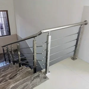
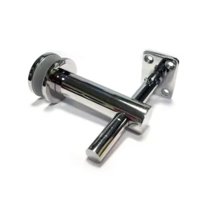
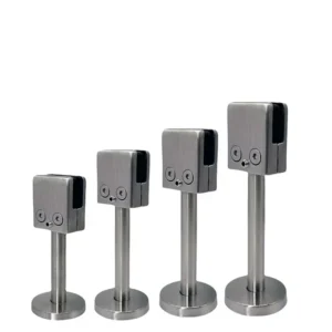
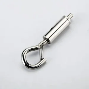
Adjustable cable tensioners are for projects where the installer needs deliberate take-up at a reachable end of each cable run. The purchasing decision is not simply “adjustable or fixed”: it is how much usable travel is required, which thread and locking detail will control that travel, what cable and opposite-end terminal are being paired, and whether the post leaves room to assemble and re-tension the fitting. A photo, sketch, cable size and approximate run length are enough to start an inquiry.
Ask ESANG about an adjustable tensioner configuration
Specify usable take-up, not body length alone
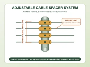
Two tensioners with similar overall lengths can provide different adjustment because their thread length, internal stop, locknut and minimum engagement differ. The drawing or quotation should show the closed length, open length, usable take-up, thread designation, adjustment tool interface and minimum permitted engagement. It should also define the intended starting position when the cable is first installed.
A practical installation normally preserves travel in both directions: enough closing movement to build tension and enough opening movement to compensate for cutting tolerance or future servicing. Starting fully closed leaves no tightening reserve; starting near the last safe thread leaves no length correction and risks insufficient engagement. Extra exposed thread is not free capacity if it collides with a wall, post cap, trim or the next cable row.

Match the adjustment mechanism to the end interface
| 界面 | Why it may be selected | Critical checks |
|---|---|---|
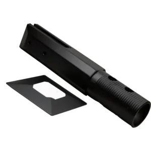
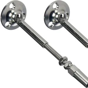
| Through-post threaded end | Compact front appearance and adjustment from the back of a terminal post | Post thickness, hole and washer detail, rear clearance, wrench swing and protruding thread |
| Surface-mounted fork, eye or pivot | Adjustment stays on the accessible inside face | Mounting fasteners, pin diameter, articulation, edge distance and line of pull |
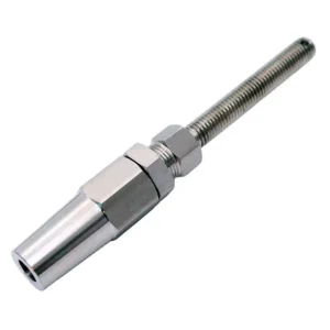
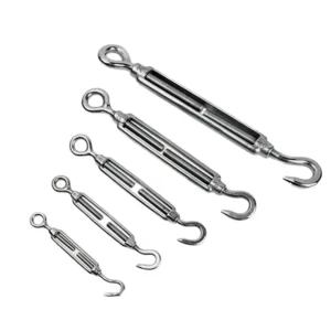
| Turnbuckle-style body | Visible adjustment between two end fittings | Right/left thread pairing, closed/open length, rotation clearance and locking method |
A fork or jaw must fit its mating tab and pin; an eye must fit the pin or shackle geometry; a surface plate must match the post face and fastener pattern. An adjustable body cannot correct a misaligned load path. If the cable meets the post on a stair angle, choose an articulating terminal designed for that plane or a properly detailed through-post interface rather than forcing a straight fitting sideways.
Pair one tensioning end with a deliberate opposite end
The other end may be a fixed terminal, stop, eye, fork, ball, threaded fitting or a second adjustable end, depending on the run and mounting details. Record the pair as one assembly. If components are sourced separately, confirm thread form, handedness, pin and hole sizes, cable interface, material requirement and finish across both ends. Matching a thread diameter but not its pitch or hand can stop assembly or damage the parts.
One adjustable end keeps the system simpler when its take-up covers the cutting tolerance and the installer can reach it. Adjustment at both ends may help center a cable or handle a difficult installation sequence, but it creates two settings that must remain engaged and locked. The choice should be visible on the run schedule rather than left to site improvisation.
Cable construction changes the correct terminal
State the cable diameter and construction together. A semi-flexible 1×19 strand and a more flexible 7×7 cable of the same nominal diameter do not necessarily use the same gripping parts or installation steps. The more flexible cable may suit a route requiring a tighter bend, while a straighter railing run may use a stiffer construction; the project specification and the exact fitting instructions decide the match. Do not use another manufacturer’s compatibility chart as proof of the ESANG configuration being quoted.
The quote should also say whether cable is included, cut to finished length, supplied in bulk or excluded. If cable and tensioners come from different sources, establish who confirms fit and which cut preparation, insertion depth or termination inspection applies.
Locking and access are part of adjustability
Ask how the final setting is retained: a locknut, opposing nut, captive feature or another stated method. Thread-locking compounds should not be assumed; if one is specified, it must suit the material, service conditions and maintenance plan. Stainless threads may also require a controlled assembly practice to reduce galling, based on the exact product instructions.
Map the wrench path before post fabrication. Through-post hardware needs usable space behind the post for washers, nuts and tools. Surface-mounted hardware needs clearance around the body or hex flats. Concealing an adjuster before final tensioning turns a serviceable feature into an inaccessible one.
Swaged and swageless ends require different site plans
A swaged cable end is permanently formed onto the cable with a matched hydraulic or hand process, either before delivery or in the field. Confirm the machine or tool, die, number and position of compressions, inspection method and finished cable length. A swageless cable tensioner uses a mechanical cable connection instead, but still requires the specified cable cutter, clean end preparation, assembly tools and exact gripping components.
Neither route is automatically better. Factory-swaged assemblies reduce field termination work but demand reliable finished dimensions. Field assembly tolerates late measurements but shifts compatibility and workmanship control to the installer. “Swageless” does not prove tool-free installation, reuse or universal cable fit.
Know when this is not the right adjacent category
- Use 缆索张紧系统 when the whole end-pair and hardware schedule are still undecided.
- Use multi-angle cable tensioners when stair pitch or an angled end interface is the dominant constraint.
- Request a documented heavy-duty turnbuckle only when an exact load basis, end form and rated configuration are required; the name alone is not a capacity.
Define the supply line and prevent mismatches
An adjustable tensioner may be supplied as a component, a matched fixed/tensioning pair, part of a cable assembly or part of a project hardware schedule. The proposed scope should itemize the cable, terminals, bodies, nuts, washers, pins, mounting screws and any dedicated tools. Post drilling, reinforcement, anchors, structural verification, installation and final railing acceptance remain site or project responsibilities unless they are expressly included.
Typical costly mismatches include too little take-up after the cable is cut, sufficient travel but no wrench clearance, a right-hand part paired with the wrong mating thread, a through-post stem that is too short for the actual post, a surface plate with an unsuitable hole pattern, and a tensioner matched to the cable diameter but not its construction. None can be solved by applying more tension.
Inquiry fields that produce a comparable quote
Send the cable diameter and construction; straight-run lengths and quantities; cable spacing if it affects access; fixed-end and tensioning-end preference; post material, profile, wall thickness and hole layout; through-post or surface-mounted interface; available space behind and beside the post; stair angle or sloped conditions; desired installation position and adjustment reserve; thread standard; locking preference; swaged or swageless assembly method; available tools; material and finish requirement; exposure; and the required supply boundary.
Ask the proposal to state cable compatibility, end-pair arrangement, closed/open dimensions, usable take-up, thread and handedness, minimum engagement, lock detail, tool access, mounting and fastener interfaces, included parts and any configuration-specific load documentation. That is what makes two adjustable tensioner proposals meaningfully comparable.