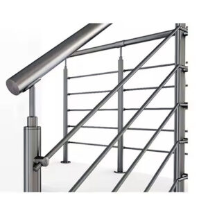
Post spacing decisions tend to travel through early design without a formal load-path check, then surface as compliance problems after installation—rails that deflect beyond acceptable limits, cable openings that exceed four inches under load, or anchor bolts that cannot be justified to a building official. Correcting any of those conditions after the railing is in place typically means removing posts, reblocking substrate, or re-engineering the entire run. The question that prevents most of that rework is not how many posts a project needs, but what force each mount must resist given the spacing chosen and the substrate it lands on. Understanding that relationship, and its effect on how suppliers interpret an RFQ, determines whether the quotes received are comparable or structurally mismatched from the start.
How Spacing Changes Load at Each Mount
Wider post spacing does not simply reduce component count—it concentrates more tributary load at each remaining mount. A post set four feet on center for a cable run carries a different base moment and anchor withdrawal demand than the same post moved to six feet, and that difference must be reconciled with the post’s actual cross-section capacity and the substrate’s ability to resist the resulting forces.
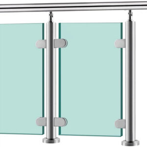
The spacing figures that circulate in commercial practice—roughly four feet on center for cable, five for glass, and six for picket or rod infill—are starting-point design figures, not code-mandated limits. They reflect the load characteristics of each infill type and the deflection sensitivity that comes with it. Cable systems transfer significant tension into end and corner posts, which biases the structural logic toward tighter spacing. Glass panels carry their own dead weight and present a large surface to lateral load, so controlling post deflection becomes the primary concern at any given span. Picket and rod infill generate less distributed tension, which allows somewhat wider spacing, but the post and anchor still need a deflection check against the applicable performance criteria.
Two details can quietly force a spacing revision even when the baseline figures look sufficient. A direct fascia mount requires drilling through the post tube, which reduces the cross-section at the bolt location and lowers the effective bending capacity at that point. Reducing spacing compensates for that loss; leaving spacing unchanged while accepting the reduced section creates a mount that may not perform as the structural layout assumes. Floating deck systems introduce a different problem: the distance between the walking surface and the mounting surface acts as a lever arm, increasing the moment delivered to the base and raising the withdrawal demand on fasteners. The post spacing itself does not change, but the load path is no longer the same as a surface mount at grade, and that distinction needs to be reflected in the anchor calculation.
One planning criterion that routinely gets overlooked: only structural posts belong in the load-path count. Spreader posts are aesthetic components positioned between structural posts to control infill alignment. Including them when calculating tributary spacing produces an artificially short apparent span and understates the actual force at each structural mount.
| 可变 | Typical Spacing / Detail | Load Path Consideration |
|---|---|---|
| 电缆填充 | 4 ft on center | Tributary load concentrates at end and corner posts; wider spacing increases force on each base attachment. |
| Glass infill | 5 ft on center | Heavier panels demand closer spacing to control post deflection and manage anchorage. |
| Picket / rod infill | Up to 6 ft on center | Wider spacing is possible but still requires a deflection check for infill control. |
| Direct fascia mount | May reduce standard spacing | Drilling reduces cross‑section; closer spacing helps keep the post within its reduced capacity. |
| Floating deck system | Spacing unchanged, but moment rises | The added distance between walking surface and mounting surface creates a longer lever arm, increasing moment and withdrawal demand on fasteners. |
| Structural vs spreader post | Structural posts carry lateral and tension loads; spreader posts are aesthetic | Only structural posts participate in the load path; spacing must count only the structural posts in the grid. |
Performance Risks From Uncoordinated Post Grids
End posts and corner posts are the most mechanically loaded positions in a cable railing run, and they are also the most likely to be under-designed when the post grid is set without a full load-path review. Each cable line terminates or changes direction at those positions, which means every tension adjustment made across the run concentrates its cumulative force there. If those posts are undersized, inadequately anchored, or set into substrate that allows rotation, they will begin to twist under load.
The cascading consequence of that twist is what makes the failure expensive. Once an end or corner post rotates out of plane, it shortens the effective span that the cable wires must cross, reducing tension in every line connected to it. Lower tension means increased sag at mid-span. Increased sag means larger clear openings between cables under normal deflection. The four-inch sphere requirement that most jurisdictions apply as a guard performance standard is evaluated after deflection, not at the as-installed resting state. A system that passes visual inspection at installation can fail that performance check once cables settle and corner posts absorb accumulated tension from use.
This failure mode is difficult to attribute to any single component because nothing breaks visibly. The posts are still standing, the cables are still attached, and the hardware shows no obvious damage. What has changed is the force distribution across the grid, and correcting it means either adding intermediate structural posts to reduce the span at corner positions, re-anchoring the end posts into stiffer substrate, or increasing post gauge to resist the combined tension without rotation. All of those corrections are significantly more disruptive after installation than before it.
The planning check that prevents this is straightforward: treat end and corner post sizing as a separate calculation from intermediate posts, and confirm that the substrate at those locations can resist the combined lateral and rotational force that the grid will generate, not just the tributary load from one span.
Fewer Posts Versus Stiffer Components
The intuition behind increasing post gauge and anchor robustness to allow wider spacing is structurally sound as far as it goes. A heavier section resists bending more effectively, and a better-anchored base reduces rotation at the mount. Both improvements extend the practical span over which a post can perform within deflection limits. The constraint that this reasoning does not address is the substrate beneath the base plate.
If the framing under the mounting surface flexes—whether from undersized blocking, inadequate bearing area, or wood that has not been assessed for the load—the post moves regardless of its own stiffness. The force path runs from the cable through the post to the base to the substrate, and any compliance in that chain translates directly into post movement. Specifying a heavier-gauge post without verifying what it is attached to can produce a system that looks robust at the component level but moves under load because the boundary condition was never checked.
The other implication of widening spans is less obvious than post gauge selection: deflection at mid-span is a function of unsupported run length, and increasing tension alone cannot correct a span that is simply too long. When a layout pushes spans wider to reduce post count, the engineering response is often to add intermediate support points, not to specify higher tension values. Higher tension increases the force on end posts and anchors without proportionally reducing mid-span sag once the span exceeds the range for which the post configuration was designed.
| Component Setup | Span Tolerance | Risk / Key Constraint |
|---|---|---|
| Light posts on marginal blocking | Narrow spans only (typically 4 ft or less) | Excessive deflection and movement; tension loss in infill. |
| Heavier‑gauge posts with robust anchoring | Tolerate wider spans (up to 6 ft with pickets) | If the framing under the base plate flexes, even strong posts can still move. |
| Any post with flexible supporting framing | Must be shortened regardless of post strength | Framing flex transfers movement; added intermediate support points are needed, not just higher tension. |
The practical decision point here is not whether heavier components are better—they often are—but whether the supporting framing has been assessed as part of the same scope. Substrate stiffness is frequently the controlling constraint, not the post specification.
Making Supplier Quotations Comparable
Most jurisdictions do not prescribe a required distance between posts for cable or other infill types. They state guard performance expectations: maximum permissible opening under load, minimum rail height, and lateral resistance that the system must demonstrate. The spacing that achieves those expectations is left to the designer. That approach gives flexibility, but it also means two suppliers quoting the same project can assume meaningfully different post grids and still consider both layouts code-conforming, as long as each one satisfies the performance criteria.
The result is that quotes can differ in post count, anchor bolt pattern, base plate configuration, and total material quantity—not because suppliers interpreted the hardware differently, but because they started from different grid assumptions. ASCE/SEI 7-22 and ASTM E935-21 establish performance-based expectations for loads and railing system behavior, but neither document tells a supplier how far apart to set posts. When the RFQ does not fix that spacing, each supplier fills the gap with their own default, and the quotes become structurally incomparable.
Mount type introduces a parallel problem. A fascia-mounted post typically uses two to three bolts, while a surface-mounted flanged post uses four. The difference affects base plate geometry, bolt layout, substrate bearing area, and unit cost. A supplier quoting fascia mount is not quoting the same structural condition as a supplier quoting surface mount, even if both are pricing the same post section. If the RFQ does not specify mount type as a fixed condition—or explicitly list both as alternates with their associated details—the cost and structural assumptions in the returned quotes will diverge in ways that are difficult to reconcile after the fact.
| Quotation Variable | Why Assumptions Diverge | What to Align in the Request |
|---|---|---|
| Post spacing | Codes generally state opening limits and performance expectations, not prescribed distances; suppliers may assume different grid layouts for the same infill type. | Specify required post‑to‑post distance or provide clear performance criteria (maximum opening under load, deflection limits). |
| Mount type | Fascia‑mounted posts use 2–3 bolts, surface‑mounted flange uses 4 bolts; bolt count and base detail affect cost and structural assumptions. | Require mount detail to be identified as fixed or clearly stated as an alternate with the associated bolt pattern and base plate configuration. |
The correction is a process step, not a product decision: resolve post grid and mount type before the RFQ is issued, or identify them as alternates with clearly stated conditions for each option.
RFQ Inputs That Must Be Fixed or Alternated
An RFQ that leaves post spacing, infill detail, mount type, or substrate condition ambiguous does not produce comparable quotes—it produces quotes that each reflect a different project. Fixing those inputs is not a matter of over-specifying; it is the minimum level of definition required for suppliers to price the same load path.
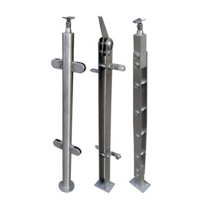
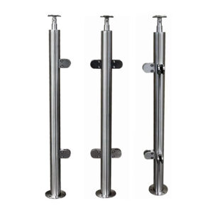
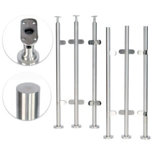
Post grid is the most consequential input to fix. The spacing affects post quantity, tributary load per mount, base plate sizing, and anchor bolt demand. Leaving it open invites suppliers to optimize toward their own preferred defaults, which typically minimize component count but may not reflect what the substrate and infill type actually require. For round stainless steel posts in 304 or 316 grade, wall thickness, outside diameter, and height interact with spacing to determine whether the post will stay within acceptable deflection at each mount position. None of those relationships are visible in a quote that does not specify the grid.
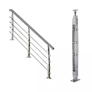
Infill spacing carries a separate but related load implication. For cable systems, horizontal cable spacing is commonly set at approximately three inches on center, producing a clear opening of roughly three and one-eighth inches at rest. That margin is deliberately sized to stay within the four-inch sphere limit after normal deflection under use conditions. If the RFQ does not state cable spacing, suppliers may assume different configurations, which changes the tension load delivered to each post and makes the resulting structural assumptions inconsistent across quotes. For the implications of post selection on cable tension management, the design considerations covered in stainless steel cable railing post systems illustrate how post configuration and tensioning requirements interact in practice.
Mount detail and substrate condition are the inputs most likely to be treated as assumptions rather than stated values. Fascia mount changes the effective cross-section at the bolt hole and may require adjusted spacing; surface mount changes the base plate footprint and bolt count. Substrate type—wood blocking, concrete, steel—affects anchor specification, bearing area, and whether an engineering check is required before the mount can be confirmed. If substrate conditions are not yet resolved at RFQ stage, identifying them as alternates with conditions is more useful than leaving them blank. A quote that requires a concrete embed is not interchangeable with one assuming wood blocking, and discovering that distinction during procurement review wastes time that should have been spent at the design stage.
| RFQ Parameter | Impact on Load Path | Typical Fixed Value or Alternates |
|---|---|---|
| Post grid (spacing) | Affects tributary load per post and quantity; wider grids reduce post count but increase demand per mount. | Fixed spacing per infill type (e.g., 4 ft cable, 5 ft glass, 6 ft picket) or state an acceptable range as alternates. |
| Infill type and cable/bar spacing | Horizontal spacing determines tension load and code‑sphere compliance; clear opening must stay within limits after normal deflection. | Cable spacing often 3 in. o.c., clear opening ~3⅛ in. at rest; specify spacing and required post‑deflection opening limit. |
| Mount detail | Mount type changes load transfer and bolt count; fascia mount may require closer post spacing. | Identify fascia, surface mount, or other as fixed, and note required bolt pattern or substrate condition. |
| Supporting structure | Substrate flex can reduce effective post stiffness, even with strong components. | State substrate type (wood blocking, concrete, steel) and any required backing or expected deflection limits; if unknown, identify as an alternate requiring an engineering check. |
The most preventable procurement problem in railing specification is not selecting the wrong component—it is issuing an RFQ before the post grid, mount detail, and substrate condition have been resolved. When those inputs are ambiguous, suppliers produce quotes that cannot be fairly compared, and the apparent cost differences often reflect structural assumptions that were never aligned rather than genuine differences in product quality or pricing.
Before a quote goes out, confirm that post spacing is stated as a fixed value or as clearly bounded alternates, that mount type is specified with its associated bolt pattern and base plate condition, that infill spacing is explicit enough to establish the tension load and code-sphere compliance margin, and that the substrate at each post location has been identified or flagged for an engineering check. Resolving those four inputs before procurement converts the RFQ from a request for estimates into a request for comparable structural proposals.
常见问题
Q: What if my project uses a proprietary cable railing kit where the manufacturer already specifies the post spacing?
A: You don’t need to calculate spacing from scratch, but you still need to confirm that the mount type and substrate conditions at your site stay within the manufacturer’s engineering assumptions. The RFQ should reference the system and ask the supplier to validate that the proposed layout will meet code-mandated performance requirements on your actual deck or balcony structure—not just on a generic test setup.
Q: After I fix post spacing and mount type in the RFQ, what should I check in the returned quotes to know they genuinely follow my load path?
A: Look for an explicit restatement of your specified grid, mount detail, and substrate condition in each proposal. The quoted post dimensions, wall thickness, anchor pattern, and base plate size should correspond to the loads that your spacing and infill demand; if these items don’t appear or are only mentioned generically, the supplier may be pricing a different structural assumption.
Q: Is there a span length beyond which increasing post gauge and anchors stops working and I must add an intermediate structural post?
A: For typical cable railing assemblies, once on-centre spacing moves significantly past about 6 ft with standard round posts, mid-span deflection tends to become the controlling limit rather than material strength. At that stage, upgrading components alone rarely restores acceptable movement, so an additional structural post—not just higher tension—is the reliable way to bring the run back within performance criteria.
Q: In total installed cost, is a layout with closer spacing and lighter posts usually cheaper than a wider layout with stiffer components?
A: Frequently, yes. The savings from eliminating a few posts are easily consumed by the need for heavier-gauge sections, stronger anchors, and the additional substrate blocking or framing reinforcement that wider spans require to control deflection. Closer spacing can also simplify installation and reduce the coordination effort around substrate verification.
Q: Is it worth defining the full load path before the RFQ for a small residential deck railing, or is that effort only justified on large commercial jobs?
A: The principle scales down. Even on a modest deck, skipping the load-path definition can produce quotes based on mismatched assumptions about mount type or blocking, leading to costly rework or compliance problems later. Stating the post grid, mount detail, and infill spacing in the RFQ adds minimal effort and makes it possible to compare bids that address the same structural conditions.