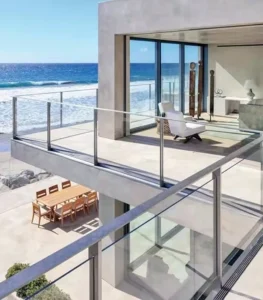
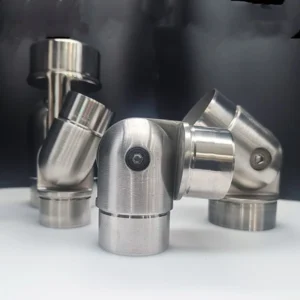
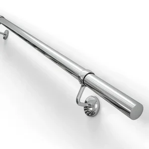
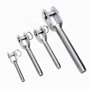
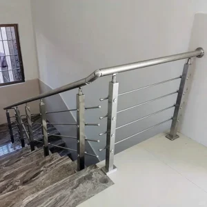
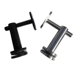
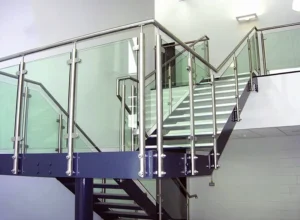
Extended-length handrail planning is mainly a segmentation, access and interface problem. The overall route may be long even when it is supplied as several controlled sections. A long manufactured section also does not create a longer allowable unsupported span. ESANG can review the route, access limits and required finish and prepare a proposed section-and-joint plan for confirmation.
Discuss an extended handrail route on WhatsApp
Separate the four lengths
Many ordering mistakes happen because four different dimensions are described as “span” or “length.” Put each one on the drawing:
- Overall route length: the total centerline distance through all straight runs, corners, slopes, landings and returns.
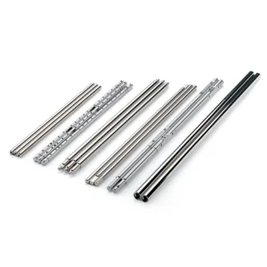
- Manufactured section length: the length of one tube or shop-welded assembly before field connection.
- Handling and delivery length: the maximum piece that can be packed, transported, lifted and moved through the site without damage.
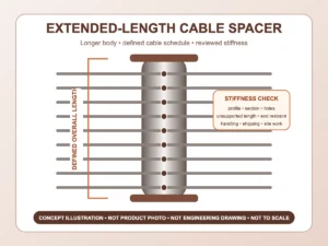
- Unsupported span or support spacing: the distance between brackets, posts or other supports. This is a design value for the complete system, not a synonym for the supplied tube length.
Ask the quotation to list the proposed manufactured sections and joint locations. The project designer or engineer remains responsible for required supports, loads, anchors and the supporting structure.

Choose a section strategy
Fewer, longer shop-prepared sections
This strategy can reduce field joints and move more alignment and finishing work into the shop. It requires reliable final dimensions and a verified route from unloading to installation. Long or irregular assemblies may be harder to protect, lift, rotate and position.
Shorter marked modules
Modular sections can simplify transport and allow site tolerance to be absorbed at planned joints. They introduce more connection points, so joint appearance, retention, inspection and any movement allowance must be agreed. Mark each module and its orientation against the approved elevation or run schedule.
Shop assemblies with controlled field closures
A hybrid plan can place shop-finished corners or returns in repeatable assemblies while leaving accessible closure joints for field fit. The drawing should identify which dimensions are fixed, which are site-verified and who completes each closure.
None of these routes is universally best. Compare total handling, access, finishing and coordination effort rather than judging only the number of joints.
Survey access before freezing the section length
Record the complete handling path, not only the final installation line:
- vehicle and unloading limits;
- door, lift, stair-core, corridor and façade-opening dimensions;
- turning space and the maximum diagonal that can pass each restriction;
- lifting points, rigging restrictions and any occupied-area controls;
- areas where protective wrapping must remain in place;
- the sequence in which adjacent walls, glazing, finishes or equipment are installed.
A section that fits the drawing may still be impossible to move into position. If access is uncertain, provide a site video or marked-up photos so the proposed split points can be reviewed before fabrication.
Keep continuity and movement distinct
Some projects require a continuous gripping surface along a stair flight or ramp run. For U.S. accessibility work, the official ADA Standards, Section 505 are one reference. Continuity of the user’s gripping path does not necessarily mean the entire route must be one manufactured piece.
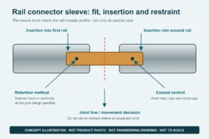
Long routes can also interact with temperature change and building movement. Mark fixed points, sliding or movement details, structural joints and interfaces with other construction on the coordinated drawing. A tight joint is not automatically a movement joint, and a longer tube does not eliminate the need to address movement where the project requires it.

Coordinate every field interface
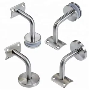
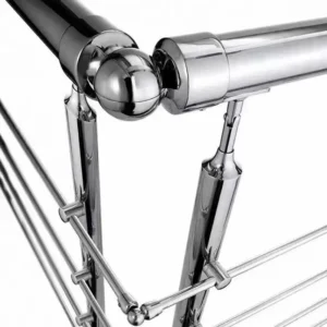
- Supports: locate posts and brackets by centerline and elevation; record the rail profile and attachment detail.
- Substrate: identify concrete, steel, timber or another supporting material and the party responsible for anchors and local reinforcement.
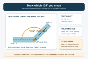
- Turns and slopes: give actual angles, centerline radii and tangent points rather than a generic “corner” note.
- Returns and terminations: show wall returns, extensions, caps and any conflict with doors, glazing or circulation.
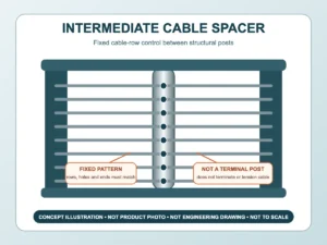
- 填充: identify adjacent glass, cable, rods or panels and separate their hardware and loading from the handrail section.
- 完成: define the finish reference, grain direction, field-repair limits and how joint areas are to match adjacent rail.
Build an auditable quote package
You can start with approximate dimensions. A production-ready package should eventually include:
- dimensioned plans and elevations with run names;
- overall route and proposed manufactured section lengths;
- rail profile, wall, grade, finish and end preparations;
- support locations and the responsible structural design criteria;
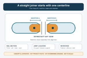
- joint type, joint location and acceptable visible transition;
- site-verified dimensions, access limits and installation sequence;
- packing marks, lifting or protection requirements and delivery destination;
- estimated quantities and required drawings, samples, certificates or inspection records.
The proposed quotation should clearly state the maximum section offered for this job, the number and type of field joints, included connectors and finishing work, and anything left to the installer. It should not imply an unsupported span, a code result or an installation outcome that has not been engineered for the project.
Common extended-length questions
Does “extended length” mean a single extra-long rail?
Not necessarily. It can describe a long route supplied as one or more controlled sections. The agreed section plan should follow fabrication, transport, access and finish requirements.
Can a longer section reduce support posts or brackets?
Not by itself. Support spacing is determined by the complete system, loads, tube properties, connections, anchors and substrate. A longer manufactured piece only changes where joints occur.
Where should joints be placed?
Prefer accessible, controllable locations that meet the visual brief and installation sequence. Avoid assuming that every landing, corner or support is automatically a suitable joint; review the actual connection and finish work.
Can ESANG quote before the final site survey?
Yes. Send the route, target profile, estimated sections, exposure and known access limits. The proposal can identify assumptions and the dimensions that must be site-verified before fabrication.