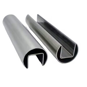
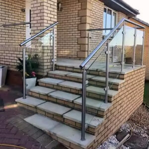
Bracket quantity commitments made before substrate conditions are confirmed create a predictable sequence of problems: anchor substitutions mid-installation, deflection in the finished rail, or a rejection that requires opening up a finished wall to add blocking that should have been specified at rough-in. The cost is not just rework labor — it is the compounding delay of a failed inspection on a project where the wall finish is already complete. The resolution sits upstream, in verifying wall type, confirming anchor compatibility, and setting spacing intervals only after those variables are known. What follows helps a buyer, specifier, or installer judge which inputs must be documented before a bracket order becomes a procurement commitment.
Bracket spacing before purchase quantities are fixed
A 4-foot maximum bracket spacing is a practical ceiling from product and industry application guidance, not a universal regulatory floor that applies regardless of conditions. Treating it as a default — applied uniformly across a project before the substrate, tube profile, and load path have been reviewed — is where deflection problems and loose fixings originate. The 4-foot figure only holds when the wall behind each bracket can actually develop the pullout resistance the anchor requires, when the tube profile has enough wall thickness to span the distance without mid-span deflection under load, and when the load path from rail to structure is genuinely continuous at that spacing. When any of those conditions is weaker than assumed, the appropriate bracket interval tightens.
The quieter trade-off in this calculation is bracket count versus visual interruption and installation labor. Tighter spacing distributes load more reliably across the wall and reduces the stress concentration at any single fixing point — but it adds brackets to the visual rhythm of the run and adds installation time proportionally. Wider spacing looks cleaner and reduces hardware cost, but it concentrates the load path demand at fewer anchors and places higher bending demand on the rail between them. Neither direction is automatically correct; the right spacing comes from knowing what the substrate will support and what the rail profile will tolerate across the span. Setting spacing before those inputs are confirmed means ordering to a number that field conditions may not validate.
ASTM E894-88 provides a useful frame for thinking about anchorage performance expectations in permanent metal railing systems — its testing approach treats the anchor-to-substrate connection as the limiting condition, not the bracket geometry alone. That framing is useful when evaluating whether a proposed spacing plan actually transfers loads back to structure or whether it is distributing stress across connections that cannot reliably carry it.
Each factor in the spacing decision carries its own verification requirement before quantity is fixed.
| 系数 | Common Oversight | 需要验证的内容 |
|---|---|---|
| Wall substrate type | Assuming the same spacing works for all substrates (wood, steel stud, concrete). | Substrate‑specific anchor pullout ratings and allowable bracket spacing per substrate. |
| Rail profile and run length | Ignoring how tube diameter and wall thickness influence deflection across the span. | Maximum unsupported span for the selected rail profile to meet deflection limits. |
| Load expectation (handrail load path) | Placing brackets without considering point‑load or cantilever paths. | That the planned spacing transfers expected handrail loads (vertical/horizontal) back to structure. |
| Anchor access behind finish | Setting bracket centers before confirming stud or blocking locations. | That each bracket aligns with adequate structural backing; no drywall‑only anchors. |
Over-ordering against a generic spacing figure is recoverable. Under-ordering after a substrate mismatch is discovered mid-run means a field delay while additional brackets and compatible anchors are sourced — a situation that is difficult to manage when the rail installation is on the critical path.
Wall substrate and backing requirements behind load transfer
Anchor selection has to precede bracket type confirmation, not follow it. A bracket’s load path is only as strong as the connection between the anchor and the substrate behind the finish surface — and that connection is determined by substrate material, not by the bracket itself. Wood stud, steel stud, and concrete each require a different anchor class, and each carries a different pullout resistance profile under the lateral and vertical loads a handrail delivers.
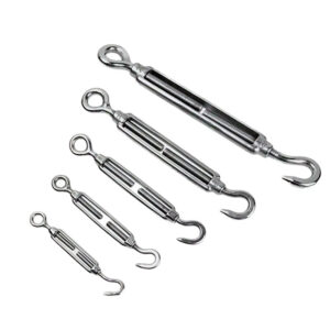
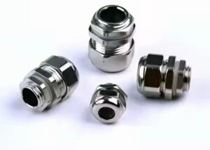
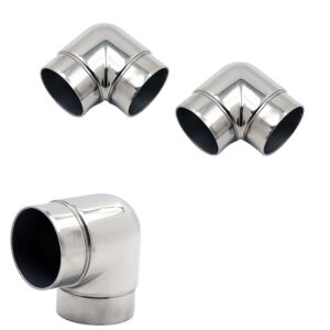
For concrete and masonry substrates, lag shield anchors are the appropriate selection for this application; for steel stud construction, toggle anchor bolts address the hollow-cavity condition where direct thread engagement into the stud is either insufficient or inaccessible. Wood stud substrates require their own anchor selection based on stud condition and the load the bracket is expected to transfer. These are not interchangeable choices. A toggle bolt used in a wood stud wall and a lag shield driven into steel framing will not develop the pullout resistance that either application demands, and that inadequacy may not surface until the rail is loaded by a user rather than during installation inspection. The failure mode is not always dramatic — it can present as a bracket that moves slightly under load, which creates a loose-feeling rail that passes visual inspection and fails when tested.
Backing condition behind the finish is a separate question from substrate type. Even when the substrate is nominally correct — concrete behind tile, wood framing behind drywall — the backing behind each specific bracket location must be confirmed. A drywall-only fixing at any point in the run creates a weak link in the load path regardless of how well the adjacent brackets are anchored. If blocking was not installed at rough-in at the locations the bracket layout requires, that gap has to be resolved before the finish is closed, not after. This is the sequencing failure that forces the most expensive rework: discovering that bracket centers fall between studs after the wall finish is complete.
The mechanical properties of fasteners in corrosion-resistant stainless steel — including the grade-to-grade differences relevant to anchor selection for exterior or chemically exposed substrates — are addressed in ISO 3506-1:2020, which serves as a background reference for fastener specification rather than a prescriptive installation rule. For project teams specifying anchor hardware for exterior wall substrates, the fastener grade consideration is separate from but related to the bracket grade decision discussed later.
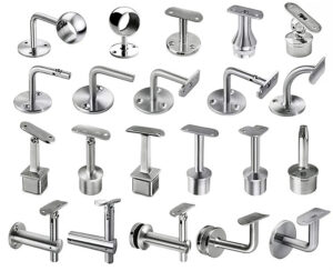
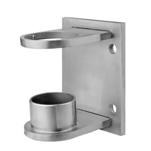
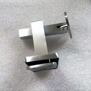
Projection details that affect grip clearance and installation speed
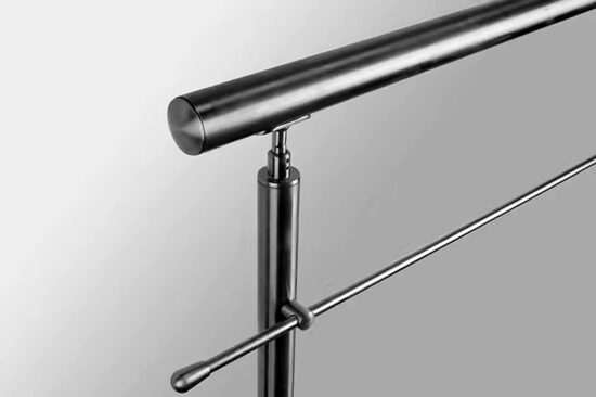
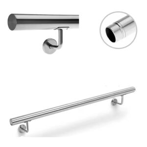
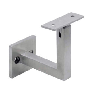
Bracket projection is a layout geometry input before it is an aesthetic consideration. The distance from the wall face to the centerline of the supported rail determines whether the grip clearance between rail and wall surface meets the design requirement — and whether that requirement holds at inspection. A wall-mount bracket that delivers a 1‑9/16″ gap between the wall surface and the top of the rail sits at the design figure aligned with ADA’s 1.5″ minimum clearance requirement. That 1/16″ of margin is narrow; it means that any installation condition that reduces the effective projection — a thick wall finish applied after bracket placement, a rail that is not centered in the bracket saddle, or a bracket seated against an uneven surface — can pull the as-built clearance below the required floor.
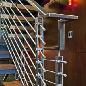
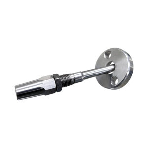
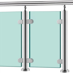
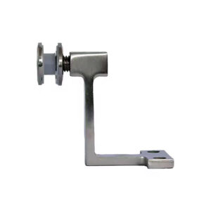
Post-mount bracket geometry introduces a different planning input. A post-mount configuration that projects 3-1/2″ from the post face to the center of the bracket affects the grip geometry along the rail run and the lateral setback of the rail from the post centerline. That dimension needs to be verified against the actual rail run geometry before the bracket model is committed to — a projection that works geometrically in plan may create interference or inadequate clearance at a stair transition or corner detail where post and rail angles converge. Discovering that mismatch after brackets are ordered and wall mounting locations are set is a rework problem, not a field-adjustment problem.
The installation speed implication is less obvious but practically significant. Brackets with projection geometry that is compatible with the substrate mounting depth and the rail profile install cleanly on the first pass. Brackets specified without confirming that the projection aligns with the finished wall surface depth — particularly in tile or cladded wall assemblies where the finish adds meaningful thickness over the structural substrate — require shimming, adjustment, or remounting that adds labor and introduces alignment inconsistency across the run. For 可调节墙壁扶手支架, the ability to accommodate angle variation in the field reduces this risk at stair runs and transitions, but it does not eliminate the need to verify projection depth against the finished wall condition before the order is placed.
Failure points when bracket type ignores wall condition
The most foreseeable bracket failure pattern in exterior or exposed conditions is grade mismatch — specifying an uncoated brushed 304 bracket for a location where the environmental service classification calls for either AISI 316 or a protective-coated alternative. A brushed 304 bracket rated for indoor use will not reliably resist corrosion in exterior exposure. The failure is not sudden; it presents progressively as surface staining that moves into pitting, then into structural section loss at the bracket-to-wall interface where moisture collects and the protective chromium oxide layer is repeatedly disrupted. By the time the corrosion is visible as a structural concern rather than an aesthetic one, the bracket and its anchors may need to be replaced — a remediation that involves reopening the wall substrate.
The grade-selection trap appears specifically on projects where 304 is specified across the entire railing package for cost consistency, and the outdoor bracket locations are not flagged as a separate service-condition requirement. For outdoor applications, AISI 316 provides the molybdenum-enhanced corrosion resistance that 304 lacks in chloride-bearing or persistently wet environments. Where 316 is not specified, AISI 304 with a black PC coating may be an acceptable alternative depending on exposure severity — but that determination belongs in the specification phase, not in a field substitution after the brackets are already installed. A late-stage grade substitution also affects unit cost and lead time when the original order was priced and scheduled against 304.
Wall condition drives a second failure pattern that is distinct from grade: anchor-to-substrate mismatch in hollow or framed wall assemblies. When a bracket rated for structural load is anchored only into drywall — because stud locations were not confirmed before bracket placement was finalized — the fixing will not develop the required pullout resistance under load. This failure does not require extreme loading to surface; normal handrail use delivers lateral and downward forces that a drywall-only anchor cannot sustain over time. The bracket may appear stable at installation and become progressively loose as the anchor fatigues the substrate around it. For heavy duty wall brackets where the design intent is higher load capacity, the anchor selection and substrate backing requirement are more critical, not less — a heavier bracket with inadequate backing concentrates load at a point the wall cannot support.
These failure patterns share a common origin: the bracket type was finalized before the wall condition was confirmed. The grade mismatch and the anchor mismatch are both planning-sequence errors as much as they are specification errors.
Ordering threshold after spacing, substrate, and load path are documented
Ordering before spacing, substrate, and load path are resolved does not accelerate procurement — it introduces substitution risk, quantity error, and field incompatibility that surface at the moment installation begins. The ordering threshold is the point at which planning variables become procurement commitments, and that transition requires a specific set of confirmed inputs before it can be made responsibly.
The verification checklist covers the bracket count calculation, anchor selection, environmental service classification, and projection confirmation as a connected set — each item affects the others, and an unresolved variable in any row creates uncertainty that cascades into the order.
| Verification Item | 需要确认的事项 | Why It Matters for Ordering |
|---|---|---|
| Wall substrate and backing | Material type (wood stud, steel stud, concrete) and backing condition. | Determines anchor choice and load‑bearing capacity; affects quantity and type of brackets. |
| 锚栓规格 | Concrete/masonry → lag shield; steel stud → toggle bolt; wood stud → appropriate anchor selection. | Wrong anchor leads to pullout failure; correct anchor ensures order includes compatible fasteners. |
| Bracket spacing plan | Spacing intervals defined after accounting for substrate, rail profile, and load path; generic max 4 ft. | Prevents deflection and field rejection; sets exact bracket count for the order. |
| Tube profile and rail run | Tube OD, wall thickness, and total run length. | Influences maximum spacing and ensures bracket stock matches rail geometry. |
| Environmental service condition | Indoor‑only or outdoor exposure; outdoor requires AISI 316 or 304 with black PC coating. | Prevents corrosion failure; ensures correct grade is ordered for project lifespan. |
| Grip clearance (bracket projection) | Wall‑bracket gap ≥ 1‑9/16″ meets ADA 1.5″ min; post‑mount projection 3‑1/2″ affects layout. | Code‑compliance; avoids rework. Confirms bracket model before order. |
Two items in this checklist carry the most consequence if they remain unresolved at the time of order. The environmental service classification — indoor versus outdoor, and whether 304 or 316 is appropriate — affects both unit cost and lead time, and a grade substitution discovered after an order is placed is a sourcing problem, not just a specification correction. The anchor specification tied to substrate type determines whether the bracket count in the order includes compatible fasteners or whether that hardware has to be sourced separately against a different substrate condition found in the field. A bracket order that arrives without compatible anchor hardware for the actual substrate delays installation while the correct anchor type is sourced — a delay that is straightforward to avoid when substrate type is confirmed before the order is submitted.
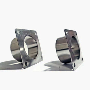
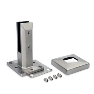
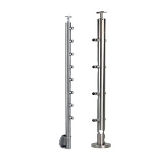
For projects with post-mount conditions alongside wall-mount runs, the projection geometry and base plate specification represent a separate verification item. 表面贴装底板 carry their own substrate and anchor requirements that should be confirmed through the same verification sequence rather than assumed to follow the wall-mount specification. Mixed mounting conditions on a single project are a common source of incomplete orders when the two bracket types are treated as a single line item rather than as independent specifications.
The practical implication across this sequence is that bracket type, spacing, anchor, and grade are not independent choices — each is a function of what the wall condition and project environment actually require. The 4-foot spacing figure, the 1-9/16″ projection clearance, and the 316 versus 304 grade decision are all confirmed design inputs at the ordering stage, not variables that can be refined in the field without cost.
Before placing a bracket order, the minimum confirmed inputs should be: substrate material and backing condition at each bracket location, anchor type matched to that substrate, spacing intervals set after rail profile and load path have been reviewed, bracket projection verified against finished wall depth and grip clearance requirement, and environmental service classification matched to the correct grade. If any of those items remain open, the order is not ready — and the cost of resolving them after delivery is measurably higher than resolving them before. For a more detailed look at how bracket type changes based on projection and wall condition, the article on handrail bracket selection covers those decision branches in further depth.
常见问题
Q: What should happen if stud locations don’t align with the bracket spacing the rail run requires?
A: Blocking needs to be added before the wall finish is closed — this is the only reliable fix. Discovering that bracket centers fall between studs after drywall or tile is complete forces the most expensive rework sequence in a handrail installation: opening the finished wall, installing backing, and refinishing. Confirming stud locations against the proposed bracket layout during rough-in, before any finish is applied, is the only way to avoid that outcome.
Q: Is it worth upgrading all brackets to AISI 316 on a project that has both indoor and outdoor railing runs?
A: Upgrading the entire package to 316 is worth evaluating against the cost difference, but it is not automatically required for every bracket. The meaningful decision is whether indoor-rated 304 brackets are being specified into outdoor or chloride-exposed locations without a protective coating — that specific mismatch is the failure risk. For genuinely indoor-only runs, the grade upgrade adds cost without a corresponding performance benefit. The practical approach is to flag outdoor and exposed locations as a separate service-condition line item during specification rather than applying a single grade across the project without reviewing exposure by location.
Q: Can bracket spacing be adjusted in the field if substrate conditions turn out to be different from what was planned?
A: Field adjustment is possible but carries meaningful consequences. Tightening spacing after installation begins requires sourcing additional brackets and compatible anchors mid-run, which delays installation and may not be straightforward when the project is on the critical path. Widening spacing to skip a problem substrate location concentrates load-path demand on fewer anchors, which may push bending and pullout demands past what the remaining fixings can reliably carry. Neither direction is a clean resolution. The practical implication is that substrate verification before the order is placed eliminates both scenarios.
Q: How does grip clearance verification change when the wall finish is applied after brackets are mounted?
A: It becomes a risk that has to be actively managed rather than assumed. A bracket dimensioned to deliver a 1‑9/16″ gap against the structural substrate will lose effective clearance when a thick finish — tile, cladding, or built-up plaster — is applied over the face the bracket projects from. If the finish thickness reduces the as-built gap below the 1.5″ ADA minimum, the installation is non-compliant at inspection even though the bracket itself meets the dimension requirement. The fix is to confirm the finished wall depth before bracket placement is finalized, not after the finish is complete.
Q: At what point does adding more brackets stop improving structural performance and just add cost and labor?
A: The return diminishes once spacing is tight enough that no single bracket is carrying a load concentration that exceeds what the substrate and anchor can reliably transfer. Beyond that threshold, additional brackets contribute visual interruption and installation labor without meaningfully reducing stress at any individual fixing point. The practical ceiling described in the article — 4 feet under confirmed conditions — is a maximum, not a target; some substrate and load-path conditions will require tighter spacing. But reducing spacing below what the rail profile and wall condition actually require does not improve structural performance and adds cost without a corresponding engineering benefit.