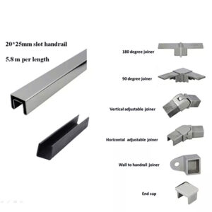
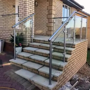
A base plate detail can look complete once it shows plate size, bolt-hole pattern, and a post symbol, yet still leave a fabricator and a site crew disagreeing about what dimension controls once the plate meets the actual slab. The drawing that resolves that disagreement before fabrication is different from the drawing that merely documents the part. Knowing which fixed inputs, which coordination checks, and which tolerance boundaries belong on that detail determines whether the base plate arrives ready to set or becomes a field-fit problem.
在制造底板之前必须确定的图纸输入信息
A base-plate detail is a coordination document before it is a fabrication document. Its purpose is to lock the inputs that fabrication depends on so that the plate produced matches the condition it will meet, rather than a generic or assumed condition. Where those inputs are left open or implied, the fabricator has no basis for deciding hole spacing, edge distance, or plate orientation with confidence, and the detail becomes a source of ambiguity rather than a control.
The inputs that must be fixed include the plate’s own geometry, its relationship to the post it carries, and its relationship to the structure it lands on. If any one of these is described only in general terms — a plate size without a stated post centerline, or a hole pattern without a stated edge reference — the remaining dimensions on the sheet cannot be trusted as coordinated, because they were derived without a common reference point.
The condition that changes this judgment is whether the surrounding structure is fixed at the time the detail is drawn or still subject to change. Where the supporting slab, curb, or structural steel is already built and measurable, the detail can carry confirmed dimensions and the fabricator can proceed on those numbers directly. Where the structure is still being formed, cast, or finished, the detail can only carry the intended dimension, and the drawing must say so plainly rather than presenting a design figure as if it were a verified one. Carrying that distinction forward is what separates a detail that can be released for fabrication from one that still needs a field check before it is trusted.
This distinction also determines what the buyer should ask for at the point of ordering. A drawing that states its inputs as confirmed should be treated differently from one that states them as intended, and a supplier reviewing a submitted detail needs to know which category applies before committing plate stock or drilling a hole pattern that cannot be adjusted once cut.
支撑结构上的底板尺寸和立柱中心线
The base plate does not exist as an isolated part; its dimensions only make sense in relation to the post it carries and the structure it sits on. A detail that shows plate size and hole centers without also showing the post centerline and the plate’s edge orientation relative to the supporting structure gives the fabricator a shape but not a placement. The placement is what determines whether the finished assembly lands where the design intends it to land.
Showing plate size, hole centers, post centerline, edge orientation, and the relationship to the supporting structure on the same detail keeps these values from drifting apart across separate sheets. When the post centerline is drawn on one sheet and the plate’s edge relationship to the slab is drawn on another, small inconsistencies between the two can pass unnoticed until the plate is set and the post is found to be offset from where the railing run needs it. Keeping all of these references on one detail lets a reviewer check them against each other directly.
The condition that changes how much this relationship matters is the shape and orientation of the supporting edge itself. Where the post sits well inside a flat slab with no near edge, minor deviation between the assumed and actual centerline has more room to be absorbed. Where the post sits near a slab edge, an angled edge, or a curved edge, the same deviation changes the plate’s edge distance in a way that cannot be corrected without moving the post or altering the plate. The detail needs to show the actual edge condition, not a simplified or assumed one, whenever the post falls close enough to an edge for that edge condition to affect hole placement.
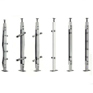
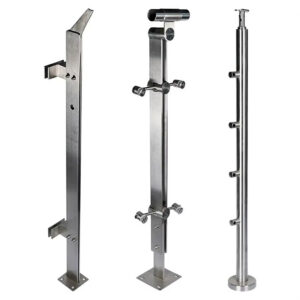
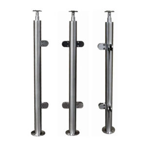
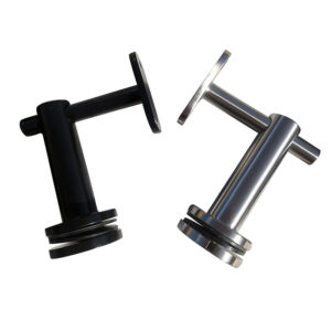
This is also where a stated product family matters to the drawing. A detail built around 表面贴装底板 carries a different relationship between plate footprint, post centerline, and structural surface than a core-drilled or embedded post condition would, because the plate sits on the finished surface rather than being set into it. The detail should identify which mounting condition applies before the post centerline and edge orientation are finalized, since the same nominal post location can require a different plate footprint depending on which mounting condition is intended.
孔中心、板边、障碍物及钻孔通道
| 协调点 | 图中应展示的内容 | 在球洞布局确定之前做出的决定 |
|---|---|---|
| 孔中心与板边 | 根据楼板边缘确定孔心的尺寸。. | 确认拟定的孔位布局与边缘关系是否协调一致。. |
| 钻孔与工具取用 | 请标明孔位所需的尺寸。. | 确认已解决预定的钻孔和工具进出问题。. |
| 相邻障碍物 | 根据孔位布局和施工通道,确定路缘石、饰面、玻璃以及相邻钢结构的位置。. | 在孔位图发布之前,先找出障碍物。. |
Once the post centerline and plate orientation are fixed, the hole pattern itself becomes the next point of coordination, and it depends on more than the plate geometry alone. A hole center that is correctly dimensioned relative to the plate can still fall too close to a slab edge for the anchor to develop properly, or too close to an obstruction for the drilling tool to reach the location at the angle the installation requires.
Edge distance is a structural and installation concern together: the drawing needs to state the hole centers in relation to the slab edge specifically, not only in relation to the plate, because the plate’s position on the slab is itself a variable until it is set. Drilling access is a separate concern from edge distance — a hole can sit at an acceptable distance from an edge and still be unreachable by the drilling tool if a curb, adjacent finish, glazing, or nearby steel blocks the approach angle or the clearance the tool needs around the hole location.
The condition that changes this judgment is what surrounds the post location at the time drilling occurs. Where the area around the post is open and unfinished, access is rarely the constraint and edge distance carries more of the coordination burden. Where finishes, glazing, or adjacent steel are already in place — or scheduled to go in before the post is set — access becomes the constraint that can override an otherwise acceptable hole pattern, because a correctly spaced hole that cannot be drilled is not a usable hole. The detail should dimension the access needed at each hole location, not assume that fitting the plate on paper means the tool can fit on site.
属于制造公差与经验证的现场条件之间的公差
| 区分 | 应说明的内容 | 决策边界 |
|---|---|---|
| 制造公差 | 确定受影响的尺寸,并说明其加工公差。. | 记录分配给制造过程的公差;在需要进行现场测量且该测量已通过验证的情况下,此记录不能替代该测量结果。. |
| 已核实的现场状况 | 确定受影响的尺寸,并将其与现场经核实的测量值对应起来。. | 防止将现场特定值视为固定的公称尺寸;它不设定制造公差。. |
| 组合对齐 | 在详图中,应将制造公差与现场相关尺寸分开标注。. | 揭示协调过程中的累积偏差,而不是将其隐藏在单一的名义布局中。. |
Every dimension on a base-plate detail carries an implicit claim about where its accuracy comes from, and that claim needs to be explicit rather than assumed. A fabrication tolerance describes how precisely the plate itself will be produced against its stated dimension; it says nothing about whether that stated dimension matches the actual condition on site. A dimension tied to a verified site measurement describes the reverse — it is only as good as the measurement taken, regardless of how tightly the plate is fabricated to it.
Treating a site-dependent dimension as though it were a fixed nominal value hides the difference between these two sources of variation, and the two variations compound rather than cancel. A plate fabricated precisely to a nominal dimension that itself was never verified against the actual structure carries the full site deviation forward into the installed assembly, undiminished by how well the plate was made. The detail needs to state, dimension by dimension, whether the reader is looking at a value the fabricator controls or a value the site controls.
The condition that changes how much this separation matters is how much of the structure exists in verifiable form when the detail is issued. Where the supporting structure is complete and measurable before fabrication begins, the detail can carry verified dimensions throughout and the fabrication tolerance becomes the only remaining variable. Where fabrication must proceed before the structure is finished or before a field measurement is possible, the detail carries assumed dimensions for the site-dependent values, and those values need to be marked as subject to confirmation rather than presented with the same confidence as a fabrication-controlled dimension. Keeping fabrication tolerances and site-dependent dimensions distinct on the same detail is what exposes cumulative misalignment for coordination instead of letting it surface only after the plate is set.
同一详图中的盖板、焊缝、排水及紧固件头冲突
| 协调问题 | 需一起显示的项目 | 释放边界 |
|---|---|---|
| 盖板能否安装到位,且不会出现接口冲突? | 盖板、焊缝和外露的紧固件头 | 仅凭锚孔的配合情况,并不能证明盖板与焊缝及紧固件头部位置协调一致。. |
| 排水路径是否已清除周围接口上的障碍物? | 排水通道、盖板、焊缝和外露的紧固件头 | 仅凭锚孔的契合度,并不能证明排水路径不存在冲突。. |
| 所有接口是否已一并审查过? | 锚固孔、盖板、焊缝、排水通道和外露的紧固件头 | 不要单独发布锚孔配合的详细图;应在同一详细图上协调其余接口。. |
A base-plate detail that resolves the anchor-hole pattern has not resolved the assembly. The anchor holes establish that the plate can be fastened to the structure; they say nothing about whether the parts that finish the assembly can occupy the same space without interfering with each other. A cover plate sized to conceal the anchors can still conflict with a weld bead left proud of the surface, or with a fastener head that sits higher than the cover’s clearance allows.
Drainage introduces a similar interface that is easy to treat as separate from the fastening detail when it is not. Where the base-plate assembly needs a path for water to escape rather than pool against the post or under the cover, that path has to be checked against the same welds, cover geometry, and fastener heads that occupy the same footprint, because a drainage path that is clear on its own drawing can still be blocked once the cover and weld details are added over it.
The condition that changes how much coordination this requires is how many of these elements are actually present at a given post location. Where a post condition has no cover plate and no drainage requirement, the anchor-hole detail may be close to sufficient on its own. Where the same post carries a cover plate, a welded connection, and a drainage path together, each of those elements can individually pass its own check and still produce a conflict where they meet, because none of them was verified against the others on the same detail. The reviewer’s task is to look at the assembly as installed, not at each interface as a separate drawing.
对协调一致的维度、接口和职责进行发布检查
Releasing a base-plate detail for fabrication means confirming that the checks already described were actually performed together, not that any single check passed in isolation. A detail can show a correctly dimensioned hole pattern, a stated fabrication tolerance, and a drawn cover plate, and still fail at release if those three were coordinated on separate passes rather than checked against the same current version of the drawing.
The release point is also where responsibility for each category of information becomes distinct. The fabricator is responsible for meeting the stated fabrication tolerance on the dimensions the detail assigns to fabrication. The party providing site measurements is responsible for the accuracy of the dimensions the detail assigns to verified site conditions. Neither party can absorb the other’s responsibility by producing a detail that blurs which dimension belongs to which source, and a release that proceeds without that distinction being resolved leaves the question of who accounts for a mismatch unanswered until the mismatch appears in the field.
Where a project’s documentation follows a structure similar to what UFGS 05 52 00 Metal Railings illustrates for metal-railing submittals, the base-plate detail sits within that same submittal and coordination sequence, though the specific tolerance values, edge distances, and acceptance criteria remain matters the project’s own specification and structural documents establish rather than something a general submittal structure supplies on its own. Similarly, where a project references a standard such as ASTM E985 for permanent metal railing systems, that reference supports the general scope of railing design and performance criteria; the field-specific dimensions and tolerances for a given base plate remain within the project’s own drawings and structural engineering, not inferred from the standard’s scope statement.
The information a buyer submits about post spacing, structural conditions, and mounting type is what allows a supplier’s configuration and quotation review to reflect the actual project rather than a generic assumption, which is why the inputs behind the base-plate detail need to be as settled as the detail itself before that information is submitted. Once a detail is released, the next decision is whether the post hardware and mounting components specified are the ones actually required for the confirmed structural and access conditions, since a released detail still depends on the mounting hardware matching what the drawing assumed.
常见问题
问: 在确定底板孔位布局之前,应确认哪些信息?
A: 在同一张协调详图上确认板尺寸、孔中心、立柱中心线、板边关系以及边缘方向。在放样图放行前,还需确定路缘石、饰面、玻璃幕墙、相邻钢结构的位置,以及钻孔和工具操作所需的空间。.
问: 图纸应如何区分制造公差与现场相关尺寸?
A: 请分别标注受影响的尺寸,并说明哪些公差适用于制造,哪些数值需要通过现场测量进行验证。应审查这些尺寸对对齐的综合影响,而不是将两者都纳入一个公称布局中。.
问: 只要锚固孔对准了,底板就算安装到位了吗?
A: 不。还应检查该细节在盖板、焊缝、排水路径和外露紧固件头之间是否存在冲突,因为即使孔位对齐,这些接口中的任何一个都可能仍存在未解决的问题。.
问: 引用栏杆规范或标准,是否就证明底板图纸符合该规范或标准?
A: 不。诸如 UFGS 05 52 00 或 ASTM E985 之类的参考资料虽有助于规划项目审查工作,但必须针对具体项目并依据要求的全文确认适用标准;仅凭引用本身并不能证明产品或图纸符合要求。.