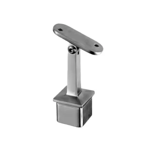
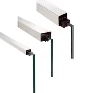
Before any railing post anchor layout is accepted on an existing slab, the concrete at each proposed post zone has to be surveyed as it is now, not as the original drawings describe it. The checks that matter are visible condition (cracks, spalls, previous repairs, old holes), measurable geometry (slab thickness, edge locations, which faces you can reach), and reinforcement information tied to that specific location rather than inherited from the as-built set. Those three findings, recorded post by post, are what the project engineer needs before any existing concrete railing anchors are confirmed, because anchor capacity depends on the base material and the hole pattern’s position within it.
Start With a Condition Survey, Not an Anchor Assumption
The survey comes first because the anchor layout is a conclusion drawn from the slab, not a starting assumption applied to it. Walk every proposed post position and record what is actually there: cracks, spalls, patches, old fixing holes, slab edges, and the faces you can physically reach with a drill and a torque wrench. That walk is the only thing that tells you whether the layout drawn in the office can survive contact with the structure.
The reason this ordering matters is mechanical. A post-installed anchor works by transferring the railing’s guard loads into the surrounding concrete, so the concrete immediately around each hole is part of the fixing. The Concrete Society’s guidance on preliminary and routine inspection describes a survey that compares the structure against drawings, records defect locations and access limitations, and identifies where closer investigation is needed — observations that inform further review rather than settle whether an anchor is suitable at that point.
Treat the survey output as evidence, not as a verdict. You are producing the information a designer needs to decide; you are not deciding on site that a given position is good. On a retrofit, that distinction keeps the work honest, because the slab you are drilling was designed for a load case that may have nothing to do with the railing now being added.
Document Cracks, Repairs, Spalls, and Previous Holes
| Existing condition | Location-specific record | Граница принятия решения |
|---|---|---|
| Crack | Photograph, dimensions, and location within the proposed post zone | Treat as observed condition evidence; do not infer anchor suitability from the observation alone. |
| Repair | Photograph, dimensions, and location within the proposed post zone | Obtain condition-specific project review before retaining the anchor layout. |
| Spall or visible deterioration | Photograph, dimensions, and location within the proposed post zone | Obtain condition-specific project review before retaining the anchor layout. |
| Previous hole | Photograph, dimensions, and position relative to the proposed hole pattern | Assess at that post location rather than treating the slab as uniform. |
Each visible defect gets photographed, measured, and located within the proposed post zone, so the record describes one position rather than the slab as a whole. APT Practice Point 16, which addresses the assessment of historic concrete structures, sets out the same discipline: verify documentary information against actual conditions, record cracking and spalling with photographs, notes and location and size annotations, and investigate undocumented repairs. It also notes that local deterioration, including at guardrail attachments, deserves location-specific documentation — directly relevant where you are replacing a railing that has been leaking rust stains down a fascia for years.
The four condition types behave differently as evidence. A crack tells you the concrete in that zone is already discontinuous, but it does not by itself tell you what an anchor there will do; that is a design question. A repair or a spalled area signals that the concrete you would drill into may not be the material the original design assumed, and a repaired or visibly deteriorated zone calls for condition-specific project review before the anchor layout at that post is retained. A previous hole matters as geometry: it is a void with a known position relative to the holes you intend to drill, and it is assessed at that post, not averaged across the slab.
Reinforcement-corrosion signs — rust staining, delamination, cracking that follows a bar line — belong in the same record. They are part of the Concrete Society’s preliminary checklist, and they point to closer investigation rather than to a conclusion you can reach with a hammer and a flashlight. Note the sign, its extent, and the post it sits near, and let the review determine what it means for the fixing.
Confirm Slab Geometry, Edges, and Accessible Faces
Measure the slab at each post position rather than reading dimensions off a drawing, because member thickness and edge distance are the geometry that post-installed anchor design depends on. Hilti’s engineering guidance on how post-installed anchors work explains that splitting can occur where minimum anchor spacing, edge distance or member thickness is not maintained, and directs those minima to the relevant European Technical Assessment for the anchor in question. It also associates concrete edge failure under shear with anchors sitting near an edge in the direction of loading — which is exactly the condition at a balcony or terrace perimeter, where guard load pushes outward toward the free edge.
So record, for each proposed post: the slab thickness you can confirm, the distance from the proposed hole pattern to every free edge, and whether the edge is a formed face, a saw-cut, a nosing, or a drip detail that reduces effective thickness locally. Toppings, screeds, waterproofing layers and tile beds matter here too, because the structural concrete may start well below the surface you are standing on, and the anchor’s embedment has to be measured into sound structural material.
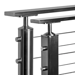
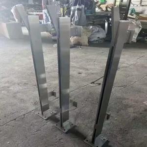
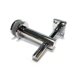
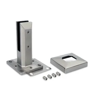
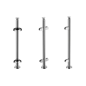
Access is a parallel constraint and it is measured, not assumed. Confirm whether the underside is reachable, because that decides whether through-bolting is even a candidate or whether the fixing must be a one-sided post-installed anchor working entirely from above. Check the clearances a drill, a dust extractor, a hole-cleaning brush and a torque wrench need at each position; a base plate detail that works at mid-slab can be unreachable 40 mm from a parapet upstand. Опорные плиты для поверхностного монтажа make these constraints explicit, because the bolt hole pattern in the plate fixes where the holes land relative to the edge, and that pattern is one of the things the review needs.
Overlay Reinforcement Findings With the Proposed Hole Pattern
| Reinforcement information basis | Label on the overlay | Граница принятия решения |
|---|---|---|
| Scan record tied to the post zone | Field-observed scan information | Use only findings tied to that location; keep areas without scan evidence identified as unknown. |
| Existing drawing | Drawing-based reinforcement information | Do not relabel drawing information as field-observed unless it is corroborated. |
| Selective exposure at the post zone | Field-observed information at the exposed location | Limit the observation to the exposed location rather than extending it across the slab by assumption. |
| No location-specific evidence | Assumed reinforcement information | Keep it marked as an assumption and send unresolved overlap with the proposed hole pattern for project-specific review. |
The overlay is a drawing of the proposed hole pattern placed over whatever reinforcement information exists at that post, with each piece of information labeled by how it was obtained. The purpose is to keep observed findings separate from assumptions carried over from the original construction, because the two carry very different weight when someone decides whether a hole can be drilled where it is drawn.
Three sources of reinforcement information behave differently. A scan record — cover meter or radar, as APT Practice Point 16 describes for locating embedded items — gives field-observed information, but only for the area actually scanned; anywhere outside that area stays unknown rather than becoming clear. An existing drawing gives you a starting expectation that still needs verification against actual conditions, which is precisely the check that practice point calls for. Selective exposure, an inspection opening, confirms what is there at the opening and nowhere else; the finding does not travel across the slab on its own.
Where no location-specific evidence exists, the honest label is assumption, and an assumed bar position overlapping a proposed hole is sent for project-specific review rather than resolved by moving the hole a little and drilling. The reason is that both outcomes of cutting a bar — loss of structural capacity in the slab and loss of the concrete condition the anchor design assumed — are design consequences, not installation ones. On a retrofit, the post position often has some tolerance along the rail line; using that tolerance to clear a scanned bar is reasonable, and doing it blind is not.
Escalate Unsuitable Zones for Project-Specific Engineering
Where the survey finds a repaired, spalled or visibly deteriorated zone at a proposed post, that post’s anchor layout stops being a field decision and goes to condition-specific project review before it is retained. The same applies to unresolved overlap between the proposed hole pattern and reinforcement, to edge distances or slab thickness that fall outside what the specified anchor’s assessment document allows, and to any face you cannot physically access with the tools the fixing method requires.
Escalation is not a delay tactic; it is the point where the information you collected becomes usable. The engineer holds the variables you cannot settle on site: the guard load case, the post spacing that distributes it, the anchor’s qualification under the relevant assessment, and whether the concrete in that zone can be treated as capable of receiving it. Hilti’s description of splitting and concrete edge failure explains why — those failure mechanisms depend on actual slab geometry and the real position of the hole pattern, so both must be in front of whoever does the review.
Whether a flagged post is released for drilling, relocated, or given a different fixing arrangement is a decision for the project’s approved procedure and its designated approver. Send the survey evidence for that post, including photographs and dimensions, and record the outcome against the post rather than carrying a verbal approval forward into the install.
Issue a Post-by-Post Existing-Condition Record
| Record component | Entry for each proposed post | Decision use |
|---|---|---|
| Post reference | Unique post identifier and proposed location | Links every photograph, dimension, and observation to one post zone. |
| Visible condition evidence | Photographs and observations of cracks, repairs, spalls, and previous holes | Shows the location-specific condition without describing the slab as uniform. |
| Geometry and access | Measured slab geometry, edge location, and accessible faces | Preserves the field inputs used to assess the proposed post zone. |
| Reinforcement evidence | Scan record, drawing reference, or selective-exposure finding, labeled as observed or assumed | Keeps evidence separate from assumptions when it is overlaid with the proposed hole pattern. |
| Review status | Anchor layout retained or pending condition-specific project review | Shows whether a repaired or visibly deteriorated zone was escalated before the layout was retained. |
The deliverable from all of this is one record per proposed post, not a general statement that the slab is sound. Each entry carries a unique post reference and location, the photographs and dimensions of any visible condition found in that zone, the measured geometry and accessible faces, the reinforcement evidence with its basis labeled as observed or assumed, and the review status showing whether the anchor layout at that post was retained or sent for condition-specific review.
The value of this structure is traceability. Months later, when someone asks why post 7 was moved 120 mm or why posts 3 to 5 use a different base plate detail, the record shows the condition that drove it and the evidence behind the decision. A package organized this way also feeds directly into the installation evidence that follows — the anchor details, base plate setting and site tolerances recorded as each post goes in — so the existing-condition survey and the as-installed record describe the same post positions in the same terms.
For the supplier discussion that follows the survey, have the marked-up post layout with measured edge distances and confirmed slab thickness, the base plate bolt hole pattern you intend to use, the scan or exposure findings with their coverage shown, the exposure conditions driving the stainless grade and finish, and the list of posts still pending review. With that in hand, the conversation about base plates, анкерные системы and post spacing can proceed on the geometry that actually exists rather than on the geometry the original drawings promised.
Часто задаваемые вопросы
Вопрос: Does concrete that looks undamaged automatically qualify for a new railing post anchor?
A: No. A clean visual appearance addresses only visible surface conditions. The post zone still needs location-specific checks for slab geometry, edge position, accessible faces, and reinforcement evidence against the proposed hole pattern; any unresolved item should remain identified rather than treated as suitable by default.
Вопрос: Can one surveyed post zone represent every post along the same railing line?
A: Only if the project review establishes that the relevant conditions are consistent. Cracks, repairs, previous holes, slab edges, access, and reinforcement evidence can vary by location, so observations should stay linked to each proposed post until that consistency is confirmed.
Вопрос: What should the team do when a drawing conflicts with a scan or selective exposure?
A: Keep each source separately labeled, record the exact location covered by the field observation, and show the conflict on the proposed hole-pattern overlay. Do not convert the drawing or a limited observation into a definitive slab-wide condition; send the unresolved post location for project-specific review before retaining the pattern.
Вопрос: How should an inaccessible face or an area without location-specific reinforcement evidence be handled?
A: Record the access or evidence gap as an unknown, not as proof that the zone is clear. If that unknown could affect the proposed hole pattern or the assessment of the post zone, keep the anchor-layout decision pending until the project-specific review determines what additional information is needed.