Рельсовые соединители
Рельсовые соединители
Choose a rail connector from the joint geometry
A rail connector must match more than the direction of travel. Straight and angled joints depend on the rail profile, outside and inside dimensions, wall thickness, actual angle, visible-joint preference and final fixing method. Use the current product routes below to describe the joint, then require the proposed connector geometry to be shown against the rail section.
Discuss a rail joint on WhatsApp
Five current product routes
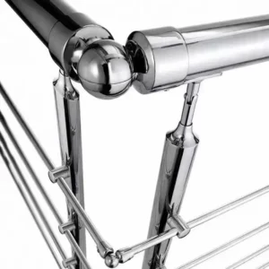
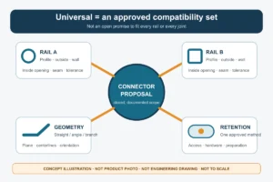
Use as a review route when a general or mixed rail-joint problem does not yet fit another family. “Universal” does not prove fit with every tube profile, size, wall thickness or fixing method.
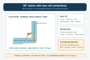
Use for a specified right-angle route. Confirm whether the angle refers to rail centre-lines or end faces, plus profile, bend/corner envelope and visible joint treatment.
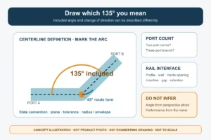
Use when the project drawing calls for this angled transition. The product name is a route; verify the actual geometry, orientation and interface before ordering.
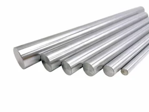
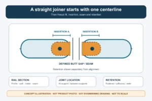
Use to continue two aligned rail sections. Provide the actual section and whether the joint is internal, external, visible, concealed, welded or mechanically retained.
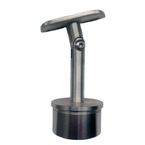
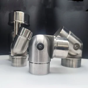
Use for a defined variable or non-standard set angle. Confirm whether adjustment is only during installation, the permitted range and the final locked condition; do not infer movement in service.
Define six joint fields before comparing connectors
Field — Provide — Why it matters
Rail profile — Round, square, rectangular or custom cross-section with dimensions — Connector geometry must seat inside, around or against that exact profile.
Inside fit — Inside dimensions, wall thickness, seams and corner radii where an internal connector is considered — Equal outside sizes do not guarantee equal internal space or insertion fit.
Direction and angle — Plan/elevation sketch with actual centre-line directions — It distinguishes straight, fixed-corner and variable-angle routes and prevents mirrored or rotated mismatches.
Joint appearance — Visible connector, concealed insert, weld-finished joint or another defined outcome — It changes connector type, site work, surface finishing and inspection access.
Retention method — Permitted weld, screw/pin, clamp or another project-specified method — A connector body is incomplete without an agreed way to keep the joint in its final position.
Support and route — Nearest brackets/posts, rail function, section lengths and installation sequence — Joint location and assembly access must suit the complete supported rail route.
Quick routing examples
• Two cut sections continue on one axis: start with Straight Rail Joiners and provide the rail cross-section plus desired joint visibility.
• A balcony rail turns a true right angle: start with 90 Degree Rail Corners and show the available corner envelope and route orientation.
• A landing or layout uses a specified oblique turn: start with 135 Degree Corner Connectors only when that geometry matches the drawing; otherwise request an angle-specific review.
• The angle is set on site: start with Flexible Rail Connectors and state the required range, set angle, access and final locking method.
Do not place a joint only where stock lengths happen to end. The project team should review support locations, route continuity, fabrication, installation sequence and any code or structural responsibility for the complete rail assembly.
What the proposed configuration should state
• current product route and connector drawing or marked dimensions;
• matching rail profile, relevant outside/inside dimensions and wall thickness;
• joint angle and orientation, with clear reference points;
• internal/external and visible/concealed relationship;
• retention or welding method, included fasteners and required site work;
• proposed material grade, finish, quantity and packaging basis;
• open dimensions and system checks that remain before production.
A rail offcut photo beside a dimensioned sketch can start route selection. A final fit still requires the actual cross-section and joint geometry.
Похожие посты:
What Should Be Included at Handrail Ends: Returns, End Caps or Open Coordination Points?
Distinguish handrail returns, end caps and unresolved end interfaces, then schedule each termination by function, adjoining construction and supply responsibility.
Factory-Cut or Site-Trimmed Handrails: Which Release Method Fits the Available Dimensions?
Choose factory-cut or site-trimmed handrails by checking dimension status, datums, mating allowances and the finish work attached to each cut.
Handrail Tube Only or a Complete Component Package: What Should the Supplier Quote Include?
Compare tube-only and component-package handrail quotes by separating fittings, fabrication, mounting interfaces, finish work and delivered quantities.
Continuous or Sectional Handrail Supply: Which Split Strategy Fits Transport and Site Assembly?
Compare continuous and sectional handrail supply using delivery access, joint locations, mating details and section identification before fabrication release.
Where Should a Handrail Change from Wall-Supported to Post-Supported Along a Mixed Route?
Choose a handrail support change by comparing wall and post interfaces, preserving the gripping path and locating the transition on coordinated drawings.
Панели с сеткой ровной, наклонной или с переходом от наклонной к ровной: какая геометрия подходит для каждого участка перил?
Выберите одну из следующих геометрий сетчатых панелей: ровная, наклонная или наклонная с переходом в ровную — в зависимости от участка ограждения, ориентации узора, соединительных элементов и проектных чертежей.
Проекты Эсанга

Сертификат Эсанга
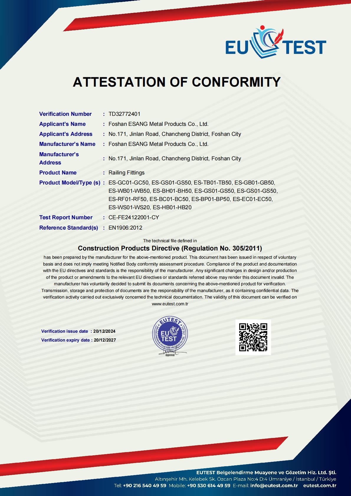
Компания Foshan ESANG Metal Products с гордостью поддерживает сертификация CE (Верификационный номер TD32772401) в соответствии с Директивой о строительной продукции (Постановление № 305/2011), что подтверждает нашу приверженность высочайшим европейским стандартам безопасности и качества.
Сертифицированный ассортимент продукции:
Наш обширный ассортимент фурнитуры для перил, включающий зажимы для стекла, натяжители, кронштейны, настенные крепления, опорные башмаки, фурнитуру для перил, кабельное оборудование и компоненты для столбов, отвечает требованиям EN1906:2012 стандарты, обеспечивающие целостность конструкции и надежность работы всех установок.
Что это значит для вашего проекта:
✓ Полное соответствие нормативным требованиям для европейского и международного рынков
✓ Независимая проверка безопасности и долговечности
✓ Документационная поддержка архитектурных спецификаций
✓ Гарантия качества от третьей стороны
Сертификация действительна до 2027 года | Отчет об испытаниях: CE-FE24122001-CY
Проекты Эсанга

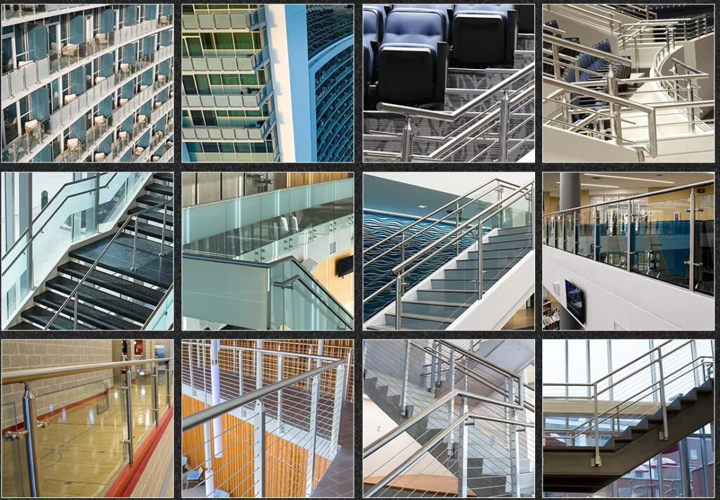
Справочные продукты