Order the sleeve from the rail’s inside geometry
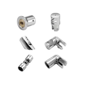
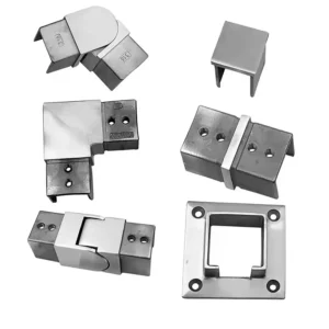
A rail connector sleeve aligns two rail sections across a joint. The critical fit is between the sleeve’s outside profile and the rail’s inside opening, including wall thickness, weld seam and corner radius. Send an end-on rail sketch or sample dimensions with the route and joint location; an outside rail size by itself is not enough to select the sleeve.
Discuss a connector sleeve on WhatsApp
Match the two mating profiles
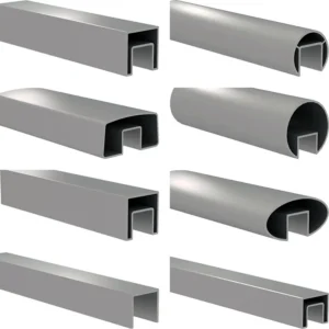
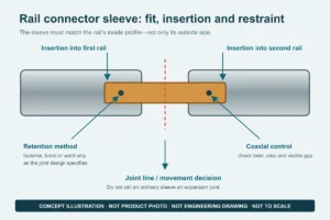
For an internal sleeve, compare the sleeve outside width, height or diameter with the rail’s actual inside opening. A nominal rail size can hide different wall thicknesses, internal seams or corner radii, so two rails with the same outside dimensions may not accept the same sleeve. If an external collar is requested, the opposite fit applies: its inside profile must match the rail outside profile and the visible step must be acceptable.
The proposed fit must allow assembly without uncontrolled forcing while limiting twist and visible step at the joint. Ask for the proposed mating dimensions and tolerance basis to be shown on the product or approval drawing.
Insertion and alignment are joint decisions
State the sleeve engagement required in each rail section, not merely the overall sleeve length. Unequal insertion, an internal obstruction or a fastener too close to the rail end can leave one side with inadequate engagement or prevent the two rail ends from meeting. The drawing should also show any center stop, access hole and the order in which rails, corners and supports are assembled.
At the visible joint, check axial alignment, rotation, surface finish direction, rail-end squareness and the intended seam. A sleeve can align the rails, but it cannot correct a twisted cut, incompatible section or unsupported joint location.

Define how the sleeve is retained
Do not assume every sleeve is fixed the same way. Depending on the specified joint, retention may involve mechanical fasteners, a bonding system, welding or a proprietary locking feature. The quotation should identify the proposed method, supplied consumables or fasteners, hole locations, surface preparation and whether the joint remains visible. The surrounding rail and supports must be compatible with that method.
A standard sleeve is not automatically an expansion joint
An ordinary rigid splice should be treated as an alignment and connection component. If the rail run needs thermal or building movement, the project detail must separately identify the movement joint, fixed side, sliding side, design gap, required movement and support locations. Some purpose-designed connectors can form part of a movement joint, but that function must be stated for the exact proposed product and assembly; it cannot be inferred from the word “sleeve.”
Compare sleeve proposals on the same fields
- Rail data: outside profile, inside opening, wall thickness, internal seam or radius, material request and finish direction.
- Sleeve data: outside mating profile, overall length, insertion on each side, stop or centering feature and proposed retention method.
- Joint data: straight, corner-adjacent or sloped location; visible gap; allowable step and rotation; nearby post or bracket.
- Scope data: sleeves, fasteners or bonding products, drilling or welding responsibility, supplied quantity and approval sample or drawing.
A sleeve is one part of a rail system. It does not by itself establish rail capacity, post spacing, support capacity, code compliance or suitability for a stated load. Those conclusions require the complete rail, sleeve, support and fastening arrangement.
Start with incomplete information if necessary
A photo of the rail end beside a ruler, a short offcut, a section drawing and an estimated joint count are enough to begin. Also mark corners, terminations and any location intended to move. The returned proposal should make the assumed dimensions explicit and list what must be confirmed before production.