Specify a 90° rail corner from the two rail centerlines
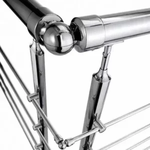
A 90 degree rail corner changes the rail direction by a right angle in a defined plane. The name does not settle the rail profile, bend radius, inside/outside fit, retention method or angular tolerance. A useful inquiry shows the two rail centerlines, the direction of travel, the corner plane and the surrounding supports, then adds the rail section and installation constraints.
To begin, send a plan or marked-up photo, one rail dimension, the approximate quantity and whether the corner is part of a handrail, top rail or another assembly. ESANG can use that input to identify the fit and drawing fields that still need approval.

Freeze the angle definition before comparing parts
Draw the centerlines and the measurement arc
Show both rail centerlines meeting at the corner and place the 90° arc on the intended side. Also show whether the corner lies in plan, rises on a slope or combines horizontal and vertical direction changes. A perspective photograph can hide the actual plane, so use a plan/elevation sketch or two views when the run is not flat.
State the allowed angular and alignment tolerance
The product name is a nominal geometry, not a promise that every project accepts the same deviation. Put the permitted angle, twist, step and butt gap on the project drawing. If the as-built corner is not a true 90°, decide whether the route should be measured as a different fixed angle or handled by a separately defined limited-adjustment connector.
Separate centerline angle from visible radius
Two connectors can create the same 90° direction change with different centerline radii and outside envelopes. Radius affects the corner’s footprint, rail cut-back, clearance and appearance. Ask the proposed drawing to show the centerline intersection or radius, overall envelope and where the rail ends meet the connector.
Five choices determine whether the corner will assemble
| Choice | Quels sont les changements ? | Field to approve |
|---|---|---|
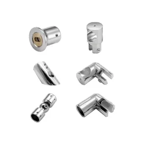
| Corner construction | A one-piece elbow, connector body or fabricated rail corner creates different seams, preparation and access. | Proposed form, visible joints and supplied pieces |
| Profilé de rail | Round, square and rectangular rails need different mating geometry; nominal size alone may hide corner radii or a weld seam. | Section drawing, outside dimensions, wall thickness and inside opening |
| Internal or external fit | An internal spigot is controlled by the rail’s inside opening; an external socket is controlled by the outside profile and creates a visible transition. | Mating dimensions, engagement on both legs and resulting step |
| Fidélisation | Set screws, through-fasteners, adhesive or welding require different holes, consumables, tools and inspection. | One approved method, access, hardware/consumables and site operation |
| Finish continuity | Grain direction, polish, seam and fastener positions affect the visible result and a graspable surface. | Finish sample/reference, seam condition, gap and fastener orientation |
Check rail fit from both sides of the joint
For an internal connector, provide wall thickness and the minimum clear inside opening on each rail leg. A longitudinal weld seam can interfere with insertion even when the nominal outside diameter matches. For an external socket, provide the actual outside size and profile, plus the acceptable visible step. If the two rails differ, identify each side separately; do not assume a nominal adapter is symmetrical.
Define insertion or overlap for both legs, rail-end squareness, deburring and the intended butt gap. A connector that bottoms out before the rail reaches its set position can move the centerline away from the drawing. A large unplanned gap can expose the spigot or break finish continuity.
Choose retention with the installation sequence
Mechanical retention
Ask the offer to identify screws, pins or through-fasteners, their hole pattern and which side remains accessible after surrounding rails and supports are installed. A concealed fastener concept may be unsuitable if the second rail closes the only tool path.
Adhesive bonding
If bonding is proposed, freeze the approved mating clearance, surface preparation, adhesive/primer, coverage, cure conditions and temporary holding method. Do not treat adhesive as an automatic substitute for a mechanical or welded joint.
Welding
If the corner is welded, the scope should state whether welding and finish restoration occur in the factory or at site, and what rail preparation is required. Hot-work restrictions, distortion control and the approved finished appearance must be coordinated separately.
Place the corner within the complete rail system
Mark adjacent brackets, posts and rail joints on the layout. The nearest support, unsupported rail length and load path can influence whether a corner location is acceptable. The connector alone does not establish the performance of the handrail or guard: rails, supports, fasteners, anchors, substrate and installation remain part of the completed-system responsibility.
When a safety-related application needs evidence, request documents that apply to the proposed rail section, corner configuration, retention and support condition. A generic material grade, a connector photo or a rating from another assembly is not a substitute.
Factory and site boundaries to itemize
| Champ d'application | Quotation should identify | Not included unless listed |
|---|---|---|
| Corner body | Nominal centerline geometry, tolerance, envelope, mating dimensions, proposed material/finish and quantity | Connected rails, brackets and posts |
| Retention set | Included fasteners, inserts or specified consumables and required rail preparation | Site tools, drilling, bonding or welding operations |
| Rail preparation | Whether rail is supplied, cut, drilled, slotted, welded or finished at the factory | As-built measurement and correction of existing rails |
| System work | Any matched support/interface expressly included | Anchors, substrate review, structural design, installation and approval |
Inquiry checklist
You can start with incomplete information. Send:
- a plan, marked-up photo or simple sketch showing the two centerlines and 90° arc;
- corner plane, direction of travel, centerline radius or available envelope;
- rail profile, outside dimensions, wall thickness, inside opening and weld-seam location;
- internal or external fit preference, insertion each side and acceptable butt gap;
- retention preference, tool access and any hot-work or adhesive restrictions;
- finish reference, exposure, adjacent materials, approximate quantity and replacement/new-work status;
- system role, adjacent support locations and project criteria.
The proposal should return the exact geometry, angular tolerance, mating/engagement dimensions, retention set, rail preparation, finish, included items, exclusions and approval point. Compare those fields before comparing body-only prices.
Frequently asked questions
Is a 90° corner always a horizontal turn?
No. It may be a plan corner, a vertical transition or another orientation. Show the plane and both rail directions so the connector is not rotated into the wrong application.
Can I select it from outside diameter alone?
Not reliably. Internal fits need the inside opening, wall thickness and weld-seam clearance. External fits still need the actual outside profile and acceptable visible step.
Should the corner be fixed or adjustable?
Use a fixed 90° definition when the project geometry is established and within its stated tolerance. Use an adjustable option only when its finite range, final angle, locking method and installed role are explicitly defined.
Does a 90° body prove the installed corner meets the project load?
No. Performance belongs to the proposed connector together with the rails, retention, supports, anchors, substrate and installation. Ask for configuration-specific review against the project criteria.
Send the corner geometry you have
A rough plan, one known rail dimension and a quantity range can start the discussion. The useful next step is not a generic right-angle part; it is an offer that fixes the plane, centerlines, tolerance, radius/envelope, rail interface, engagement, retention, seam and scope split.