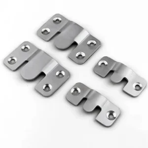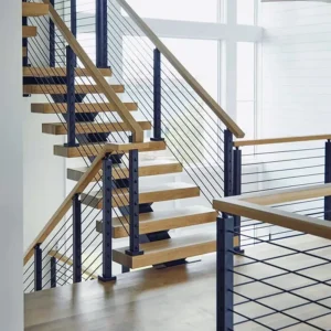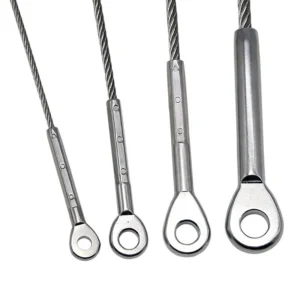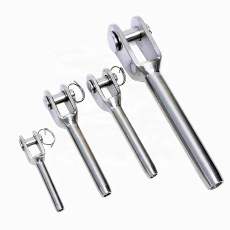
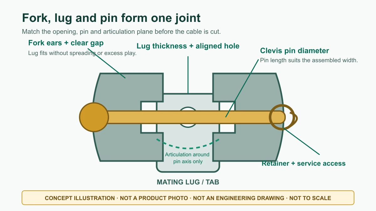
A fork end cable terminal uses two clevis ears and a removable pin to straddle a mating lug or tab. It is a useful serviceable connection when the fork opening, lug thickness, pin, holes and articulation plane are designed as one joint. The fork shape does not make it universally compatible, and the fork alone does not determine how the cable is attached or tensioned.
Request a Fork End Terminal Quote
Match the complete clevis joint
The mating part must fit between the fork ears without forcing them apart and without excessive side clearance. Pin diameter must match both fork holes and the lug hole, and the pin length must suit the assembled width and retaining feature. State whether the pin uses a clip, ring, cotter, threaded retainer or another documented method.

| Joint field | What to define | Mismatch consequence |
|---|---|---|
| Fork opening | Clear gap between ears, lug thickness and any controlled side clearance | A thick lug spreads the fork; a thin lug allows impact, tilt or poor load sharing |
| Pin connection | Pin diameter, usable length, hole diameters, head and retention method | An undersized pin creates movement; an oversized pin cannot be assembled without damaging holes |
| Articulation | Required cable angle and the plane in which the clevis may rotate | Forcing movement across the fork ears introduces side load and binding |
| Cable-side termination | Swaged socket, mechanical grip, threaded body or finished assembly | The fork can fit the lug while the cable diameter, construction or attachment process is wrong |
A fork is not a universal swivel
A conventional clevis rotates around its pin in one primary plane. Align the lug and cable run with that plane. If the site requires movement in another direction, specify a suitable articulated receiver or another end form rather than twisting the fork. For stair cable, show the actual cable angle, lug orientation and nearby post geometry.
The pin should bear on aligned holes; it should not be used to pull a misaligned bracket into position. Confirm that the pin can be inserted and removed after the post, wall finish, glazing or adjacent cables are installed.
Separate cable attachment from fork geometry
Provide cable diameter and construction, such as 1×19, 7×7 or another specified lay. If the fork has an integral swage socket, define factory or field swaging, matching terminal bore, tool/die, insertion and inspection. If a fork screws onto a threaded cable terminal, define thread series, size, pitch, hand, engagement and locking. If the cable is held mechanically, include every internal grip part and the approved installation tool.
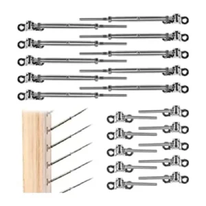
Do not assume that every fork shown with a tubular body is ready to receive loose cable. The quotation should state whether the product is a bare fork, a fork plus threaded adjuster, a cable terminal, or a finished cable assembly.
Decide fixed-end and tensioning-end roles
A simple swaged fork generally acts as a fixed end. A fork attached to a threaded body or turnbuckle may provide adjustment, but only the proposed design can establish its usable travel. Show the opposite-end fitting and initial adjustment position on the cable schedule. A cable run needs a defined route for tensioning; adding threads without accessible tool flats or sufficient travel does not solve that requirement.
Where the fork body includes an adjustable thread, identify the nut or body that creates tension and the device that locks the setting. The clevis pin retention is a separate issue. Both must remain inspectable.
Design the lug and support before ordering the fork
Send the lug/tab width, thickness, hole location, edge distances and orientation, plus the material and support to which it is attached. If the lug is welded or bolted to a post or bracket, that connection and the supporting structure remain project responsibilities unless they are specifically included in the proposed supply. The fork terminal’s suitability does not establish the capacity of the lug, post, anchors or complete railing.
Allow side space for the fork ears and retainer, longitudinal space for the cable socket or adjuster, and hand/tool access for the pin, clip and locknuts. A compact visual layout may become unserviceable if the pin faces a wall or the retainer is trapped behind a cover.
Exposure includes the pin and lug
Describe interior, exterior, coastal, pool, industrial, washdown or cleaning-chemical exposure. Ask the quote to identify proposed materials and finishes for the fork, pin, retainer, threaded parts and cable. Also identify the mating lug material so dissimilar-metal contact and moisture traps can be considered. The photos do not prove a stainless grade, load or service environment.
Define the complete supply package
- wire rope and cable-side attachment;
- fork body with clear opening and hole data;
- pin, head, washer/spacer if used and retaining item;
- mating lug or receiver only if expressly included;
- threaded adjuster, nuts and locking parts where specified;
- opposite-end fitting and available cable take-up;
- installation tools, inspection documents and protected packing where required.
Mark included, optional, customer-supplied and site-installed items. A “fork terminal” line item should not leave the pin or matching lug undefined.
Send these quote fields
- cable diameter, construction, source and finished-length basis;
- fork gap, ear thickness, hole and pin requirements;
- mating lug thickness, hole, orientation and support detail;
- required articulation plane and cable angle;
- cable attachment and fixed/tensioning function;
- thread and locking fields for any adjustable fork body;
- exposure, material/finish request, quantity and document needs.
Marked-up photos and estimated quantities can start the discussion. Before release, the proposed drawing should freeze the fork, lug, pin, retention, cable termination, adjustment and supply boundary.