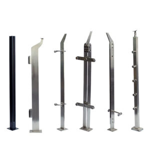
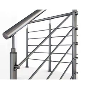
غالبًا ما تمر قرارات تباعد الأعمدة بمرحلة التصميم الأولي دون إجراء فحص رسمي لمسار الحمل، ثم تظهر لاحقًا على شكل مشكلات تتعلق بالامتثال للمعايير بعد التركيب — مثل انحراف القضبان إلى ما يتجاوز الحدود المقبولة، أو توسع فتحات الكابلات بما يزيد عن أربع بوصات تحت الحمل، أو مسامير التثبيت التي يتعذر تبريرها أمام مسؤول البناء. وعادةً ما يعني تصحيح أي من هذه الحالات بعد تركيب الدرابزين إزالة الأعمدة، أو إعادة تثبيت الركيزة، أو إعادة تصميم المسار بأكمله. والسؤال الذي يمنع معظم عمليات إعادة العمل هذه ليس عدد الأعمدة التي يحتاجها المشروع، بل القوة التي يجب أن يتحملها كل حامل بالنظر إلى التباعد المختار والطبقة التحتية التي يثبت عليها. إن فهم هذه العلاقة، وتأثيرها على كيفية تفسير الموردين لطلب عرض الأسعار، هو ما يحدد ما إذا كانت عروض الأسعار الواردة قابلة للمقارنة أم أنها غير متوافقة هيكليًا منذ البداية.
كيف يؤثر التباعد على الحمل عند كل نقطة تثبيت
إن توسيع المسافة بين الأعمدة لا يقتصر على تقليل عدد المكونات فحسب، بل يؤدي أيضًا إلى تركيز قدر أكبر من الحمل الفرعي على كل نقطة تثبيت متبقية. فالعمود الذي يتم وضعه على مسافة أربعة أقدام من المركز لمسار الكابل يحمل عزمًا أساسيًا ومتطلبات سحب التثبيت تختلف عن نفس العمود الذي تم نقله إلى مسافة ستة أقدام، ويجب مواءمة هذا الاختلاف مع السعة الفعلية للمقطع العرضي للعمود وقدرة الركيزة على مقاومة القوى الناتجة.
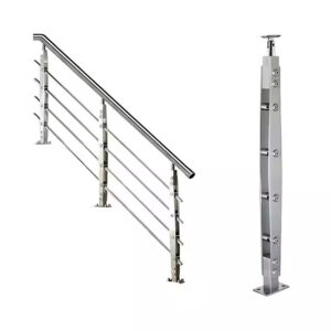
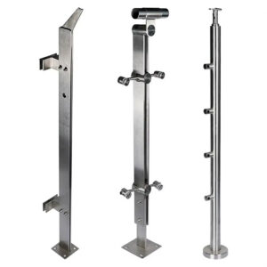
تُعد أرقام التباعد المتداولة في الممارسة التجارية — حوالي أربعة أقدام بين مراكز الكابلات، وخمسة أقدام للزجاج، وستة أقدام للحواجز الخشبية أو الحشوات القضيبية — أرقامًا أولية للتصميم، وليست حدودًا تفرضها اللوائح. فهي تعكس خصائص الحمل لكل نوع من أنواع الحشوات وحساسية الانحراف المرتبطة بها. تنقل أنظمة الكابلات شدًا كبيرًا إلى الأعمدة الطرفية والزاوية، مما يدفع المنطق الهيكلي نحو تباعد أضيق. تتحمل الألواح الزجاجية وزنها الذاتي وتوفر سطحًا واسعًا يتعرض للحمل الجانبي، لذا يصبح التحكم في انحراف الأعمدة الشاغل الرئيسي في أي مسافة بين الأعمدة. تولد الحشوات المصنوعة من الأوتاد أو القضبان توترًا موزعًا أقل، مما يسمح بتباعد أوسع نسبيًا، لكن لا يزال من الضروري فحص انحراف الأعمدة والمثبتات وفقًا لمعايير الأداء المعمول بها.
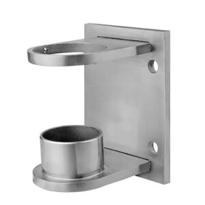
هناك تفصيلان يمكن أن يفرضا تعديل المسافات بشكل غير ملحوظ حتى عندما تبدو الأرقام الأساسية كافية. يتطلب التثبيت المباشر على الواجهة حفر ثقب عبر أنبوب العمود، مما يقلل المقطع العرضي عند موضع البرغي ويخفض قدرة الانحناء الفعالة في تلك النقطة. ويعوض تقليل التباعد عن هذا الفقد؛ أما ترك التباعد دون تغيير مع قبول المقطع المقلص فيؤدي إلى تركيب قد لا يعمل بالشكل الذي يفترضه التصميم الهيكلي. وتطرح أنظمة الأسطح العائمة مشكلة مختلفة: حيث تعمل المسافة بين سطح المشي وسطح التثبيت كذراع رافعة، مما يزيد من العزم الموجه إلى القاعدة ويزيد من متطلبات السحب على أدوات التثبيت. لا يتغير تباعد الأعمدة في حد ذاته، لكن مسار الحمل لم يعد هو نفسه كما في حالة التثبيت السطحي على مستوى سطح الأرض، ويجب أن ينعكس هذا الاختلاف في حساب المثبتات.
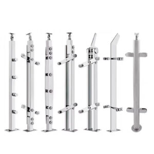
أحد معايير التخطيط التي غالبًا ما يتم تجاهلها: لا يُدرج في حساب مسار الحمل سوى الأعمدة الهيكلية. أما الأعمدة الموزعة فهي عناصر جمالية تُوضع بين الأعمدة الهيكلية للتحكم في محاذاة الحشو. وإدراجها عند حساب المسافات بين الدعامات يؤدي إلى ظهور مسافة امتداد ظاهرية أقصر مما هي عليه في الواقع، ويؤدي إلى التقليل من القوة الفعلية عند كل نقطة تثبيت هيكلية.
| متغير | المسافات النموذجية / التفاصيل | الاعتبارات المتعلقة بمسار الحمل |
|---|---|---|
| حشو الكابلات | 4 أقدام بين المحاور | تتركز الأحمال الفرعية على الأعمدة الطرفية والزاوية؛ وتؤدي زيادة المسافة بين الأعمدة إلى زيادة القوة المؤثرة على كل نقطة تثبيت بالقاعدة. |
| حشوة زجاجية | 5 أقدام بين المحاور | تتطلب الألواح الأثقل تباعدًا أقل بينها من أجل التحكم في انحراف الأعمدة وإدارة التثبيت. |
| حواجز / حواجز سلكية | ما يصل إلى 6 أقدام بين المحاور | يمكن توسيع المسافة بين العناصر، لكن ذلك لا يزال يتطلب إجراء فحص للانحراف من أجل التحكم في الحشو. |
| التثبيت المباشر على اللوح الأمامي | قد يؤدي إلى تقليل التباعد القياسي | يؤدي الحفر إلى تقليل المقطع العرضي؛ كما أن تقريب المسافات بين الأعمدة يساعد على إبقاء العمود ضمن سعته المخفضة. |
| نظام السطح العائم | لم يتغير التباعد، لكن العزم يزداد | تؤدي المسافة الإضافية بين سطح المشي وسطح التثبيت إلى تكوين ذراع رافعة أطول، مما يزيد من العزم والضغط المطلوب على أدوات التثبيت. |
| العمود الهيكلي مقابل العمود الموسع | تتحمل الأعمدة الهيكلية الأحمال الجانبية وأحمال الشد؛ أما الأعمدة الموزعة فهي ذات طابع جمالي | لا تشارك في مسار الحمل سوى الأعمدة الهيكلية؛ ويجب أن يقتصر حساب التباعد على الأعمدة الهيكلية الموجودة في الشبكة فقط. |
مخاطر الأداء الناجمة عن عدم تنسيق شبكات البريد
تُعد الأعمدة الطرفية والزاوية أكثر المواقع تعرضًا للأحمال الميكانيكية في مسار درابزين الكابلات، كما أنها الأكثر عرضة لعدم كفاية التصميم عندما يتم تحديد شبكة الأعمدة دون إجراء مراجعة شاملة لمسار الأحمال. ينتهي كل خط كابل أو يغير اتجاهه عند تلك المواقع، مما يعني أن كل تعديل في الشد يتم إجراؤه على طول مسار الدرابزين يركز قوته التراكمية هناك. وإذا كانت تلك الأعمدة أصغر من الحجم المطلوب، أو غير مثبتة بشكل كافٍ، أو مثبتة في ركيزة تسمح بالدوران، فستبدأ في الالتواء تحت تأثير الحمل.
والنتيجة المتتالية لهذا الالتواء هي ما تجعل تكلفة الفشل باهظة. فما أن يدور عمود طرفي أو زاوي خارج المستوى، حتى يقصر ذلك الامتداد الفعلي الذي يجب أن تعبره أسلاك الكابل، مما يقلل من الشد في كل خط متصل به. وانخفاض الشد يعني زيادة الترهل في منتصف الامتداد. وزيادة الترهل تعني فتحات خالية أكبر بين الكابلات في ظل الانحراف الطبيعي. ويتم تقييم متطلب الكرة ذات القطر أربع بوصات، الذي تطبقه معظم السلطات كمعيار لأداء الحماية، بعد حدوث الانحراف، وليس في حالة السكون عند التركيب. وقد يفشل النظام الذي يجتاز الفحص البصري عند التركيب في اجتياز اختبار الأداء هذا بمجرد استقرار الكابلات وامتصاص الأعمدة الزاوية للشد المتراكم الناتج عن الاستخدام.
يصعب عزو هذا النوع من الأعطال إلى مكون واحد بعينه، لأن لا شيء يتعرض للكسر بشكل مرئي. فالأعمدة لا تزال قائمة، والكابلات لا تزال موصولة، ولا تظهر على الأجزاء المعدنية أي أضرار واضحة. ما تغير هو توزيع القوة عبر الشبكة، وتصحيح ذلك يعني إما إضافة أعمدة هيكلية وسيطة لتقليل المسافة بين الأعمدة عند الزوايا، أو إعادة تثبيت الأعمدة الطرفية في ركيزة أكثر صلابة، أو زيادة سماكة الأعمدة لمقاومة الشد المركب دون حدوث دوران. وتكون جميع هذه التصحيحات أكثر إزعاجًا بعد التركيب منها قبله.
إن إجراء التحقق التخطيطي الذي يمنع حدوث ذلك بسيط وواضح: يجب معالجة أبعاد الأعمدة الطرفية والزاوية كحساب منفصل عن الأعمدة الوسيطة، والتأكد من أن الركيزة في تلك المواقع قادرة على مقاومة القوة الجانبية والدورانية المجمعة التي ستولدها الشبكة، وليس فقط الحمل الفرعي الناتج عن مسافة واحدة بين الدعامات.
عدد أقل من الدعامات مقابل مكونات أكثر صلابة
إن الفكرة الكامنة وراء زيادة سماكة العمود ومتانة التثبيت للسماح بمسافات أوسع هي فكرة سليمة من الناحية الهيكلية في حدود نطاقها. فالقطعة الأثقل تقاوم الانحناء بشكل أكثر فعالية، كما أن القاعدة المثبتة بشكل أفضل تقلل من الدوران عند نقطة التثبيت. ويؤدي كلا التحسينين إلى توسيع المدى العملي الذي يمكن للعمود أن يعمل خلاله ضمن حدود الانحراف. أما القيد الذي لا يتناوله هذا المنطق فهو الركيزة الموجودة أسفل لوحة القاعدة.
إذا انثنى الإطار الموجود أسفل سطح التثبيت — سواء بسبب استخدام دعامات أصغر من المطلوب، أو مساحة تحمل غير كافية، أو خشب لم يتم تقييمه من حيث قدرته على تحمل الحمل — فإن العمود يتحرك بغض النظر عن صلابته. يمتد مسار القوة من الكابل مروراً بالعمود إلى القاعدة ثم إلى الركيزة، وأي مرونة في تلك السلسلة تُترجم مباشرةً إلى حركة في العمود. قد يؤدي اختيار عمود ذي سماكة أكبر دون التحقق مما يتم تثبيته عليه إلى إنشاء نظام يبدو متينًا على مستوى المكونات، لكنه يتحرك تحت تأثير الحمل لأن الشروط الحدية لم يتم التحقق منها مطلقًا.
أما النتيجة الأخرى لتوسيع المسافات بين الدعامات فهي أقل وضوحًا من اختيار تباعد الدعامات: فالانحراف عند منتصف المسافة بين الدعامات يتوقف على طول الجزء غير المدعوم، ولا يمكن لزيادة الشد وحده تصحيح مسافة بين الدعامات تكون ببساطة طويلة جدًّا. وعندما يتطلب التصميم توسيع المسافات بين الدعامات لتقليل عددها، غالبًا ما يكون الحل الهندسي هو إضافة نقاط دعم وسيطة، وليس تحديد قيم شد أعلى. فزيادة الشد تزيد من القوة المؤثرة على الأعمدة الطرفية والمثبتات دون أن تقلل بشكل متناسب من الترهل في منتصف الامتداد بمجرد تجاوز الامتداد النطاق الذي صُمم من أجله تكوين الأعمدة.
| إعداد المكونات | تفاوت الامتداد | المخاطر / القيود الرئيسية |
|---|---|---|
| أعمدة الإنارة في الحجب الهامشي | المسافات الضيقة فقط (عادةً 4 أقدام أو أقل) | انحراف وحركة مفرطان؛ فقدان التوتر في الحشو. |
| أعمدة ذات سماكة أكبر مع تثبيت متين | تتحمل مسافات أوسع بين الدعامات (تصل إلى 6 أقدام مع استخدام الأعمدة الخشبية) | إذا انثنى الإطار الموجود أسفل اللوحة الأساسية، فمن الممكن أن تتحرك الأعمدة حتى وإن كانت قوية. |
| أي عمود مزود بهيكل داعم مرن | يجب تقصيرها بغض النظر عن قوة المنشور | ينقل الإطار المرن الحركة؛ لذا هناك حاجة إلى نقاط دعم وسيطة إضافية، وليس مجرد زيادة الشد. |
لا تكمن نقطة القرار العملية هنا في ما إذا كانت المكونات الأثقل وزنًا هي الأفضل — فهي غالبًا ما تكون كذلك — بل في ما إذا كان الإطار الداعم قد خضع للتقييم كجزء من نفس نطاق العمل. وغالبًا ما تكون صلابة الركيزة هي القيد المحدد، وليس مواصفات الأعمدة.
جعل عروض أسعار الموردين قابلة للمقارنة
لا تحدد معظم السلطات التنظيمية مسافة محددة بين الدعامات بالنسبة للكابلات أو أنواع الحشو الأخرى. بل تحدد توقعات أداء الحواجز: الحد الأقصى المسموح به للفتحة تحت الحمل، والحد الأدنى لارتفاع القضيب، والمقاومة الجانبية التي يجب أن يثبت النظام قدرته عليها. ويُترك تحديد التباعد الذي يحقق تلك التوقعات للمصمم. ويوفر هذا النهج مرونة، ولكنه يعني أيضًا أن موردين اثنين يقدمان عروض أسعار لنفس المشروع يمكن أن يفترضا شبكات أعمدة مختلفة بشكل جوهري، ومع ذلك يعتبران كلا التصميمين متوافقين مع القوانين، طالما أن كل واحد منهما يفي بمعايير الأداء.
The result is that quotes can differ in post count, anchor bolt pattern, base plate configuration, and total material quantity—not because suppliers interpreted the hardware differently, but because they started from different grid assumptions. ASCE/SEI 7-22 and ASTM E935-21 establish performance-based expectations for loads and railing system behavior, but neither document tells a supplier how far apart to set posts. When the RFQ does not fix that spacing, each supplier fills the gap with their own default, and the quotes become structurally incomparable.
Mount type introduces a parallel problem. A fascia-mounted post typically uses two to three bolts, while a surface-mounted flanged post uses four. The difference affects base plate geometry, bolt layout, substrate bearing area, and unit cost. A supplier quoting fascia mount is not quoting the same structural condition as a supplier quoting surface mount, even if both are pricing the same post section. If the RFQ does not specify mount type as a fixed condition—or explicitly list both as alternates with their associated details—the cost and structural assumptions in the returned quotes will diverge in ways that are difficult to reconcile after the fact.
| Quotation Variable | Why Assumptions Diverge | What to Align in the Request |
|---|---|---|
| المسافة بين المنشورات | Codes generally state opening limits and performance expectations, not prescribed distances; suppliers may assume different grid layouts for the same infill type. | Specify required post‑to‑post distance or provide clear performance criteria (maximum opening under load, deflection limits). |
| Mount type | Fascia‑mounted posts use 2–3 bolts, surface‑mounted flange uses 4 bolts; bolt count and base detail affect cost and structural assumptions. | Require mount detail to be identified as fixed or clearly stated as an alternate with the associated bolt pattern and base plate configuration. |
The correction is a process step, not a product decision: resolve post grid and mount type before the RFQ is issued, or identify them as alternates with clearly stated conditions for each option.
RFQ Inputs That Must Be Fixed or Alternated
An RFQ that leaves post spacing, infill detail, mount type, or substrate condition ambiguous does not produce comparable quotes—it produces quotes that each reflect a different project. Fixing those inputs is not a matter of over-specifying; it is the minimum level of definition required for suppliers to price the same load path.
Post grid is the most consequential input to fix. The spacing affects post quantity, tributary load per mount, base plate sizing, and anchor bolt demand. Leaving it open invites suppliers to optimize toward their own preferred defaults, which typically minimize component count but may not reflect what the substrate and infill type actually require. For round stainless steel posts in 304 or 316 grade, wall thickness, outside diameter, and height interact with spacing to determine whether the post will stay within acceptable deflection at each mount position. None of those relationships are visible in a quote that does not specify the grid.
Infill spacing carries a separate but related load implication. For cable systems, horizontal cable spacing is commonly set at approximately three inches on center, producing a clear opening of roughly three and one-eighth inches at rest. That margin is deliberately sized to stay within the four-inch sphere limit after normal deflection under use conditions. If the RFQ does not state cable spacing, suppliers may assume different configurations, which changes the tension load delivered to each post and makes the resulting structural assumptions inconsistent across quotes. For the implications of post selection on cable tension management, the design considerations covered in stainless steel cable railing post systems illustrate how post configuration and tensioning requirements interact in practice.
Mount detail and substrate condition are the inputs most likely to be treated as assumptions rather than stated values. Fascia mount changes the effective cross-section at the bolt hole and may require adjusted spacing; surface mount changes the base plate footprint and bolt count. Substrate type—wood blocking, concrete, steel—affects anchor specification, bearing area, and whether an engineering check is required before the mount can be confirmed. If substrate conditions are not yet resolved at RFQ stage, identifying them as alternates with conditions is more useful than leaving them blank. A quote that requires a concrete embed is not interchangeable with one assuming wood blocking, and discovering that distinction during procurement review wastes time that should have been spent at the design stage.
| RFQ Parameter | Impact on Load Path | Typical Fixed Value or Alternates |
|---|---|---|
| Post grid (spacing) | Affects tributary load per post and quantity; wider grids reduce post count but increase demand per mount. | Fixed spacing per infill type (e.g., 4 ft cable, 5 ft glass, 6 ft picket) or state an acceptable range as alternates. |
| Infill type and cable/bar spacing | Horizontal spacing determines tension load and code‑sphere compliance; clear opening must stay within limits after normal deflection. | Cable spacing often 3 in. o.c., clear opening ~3⅛ in. at rest; specify spacing and required post‑deflection opening limit. |
| Mount detail | Mount type changes load transfer and bolt count; fascia mount may require closer post spacing. | Identify fascia, surface mount, or other as fixed, and note required bolt pattern or substrate condition. |
| Supporting structure | Substrate flex can reduce effective post stiffness, even with strong components. | State substrate type (wood blocking, concrete, steel) and any required backing or expected deflection limits; if unknown, identify as an alternate requiring an engineering check. |
The most preventable procurement problem in railing specification is not selecting the wrong component—it is issuing an RFQ before the post grid, mount detail, and substrate condition have been resolved. When those inputs are ambiguous, suppliers produce quotes that cannot be fairly compared, and the apparent cost differences often reflect structural assumptions that were never aligned rather than genuine differences in product quality or pricing.
Before a quote goes out, confirm that post spacing is stated as a fixed value or as clearly bounded alternates, that mount type is specified with its associated bolt pattern and base plate condition, that infill spacing is explicit enough to establish the tension load and code-sphere compliance margin, and that the substrate at each post location has been identified or flagged for an engineering check. Resolving those four inputs before procurement converts the RFQ from a request for estimates into a request for comparable structural proposals.
الأسئلة الشائعة
Q: What if my project uses a proprietary cable railing kit where the manufacturer already specifies the post spacing?
A: You don’t need to calculate spacing from scratch, but you still need to confirm that the mount type and substrate conditions at your site stay within the manufacturer’s engineering assumptions. The RFQ should reference the system and ask the supplier to validate that the proposed layout will meet code-mandated performance requirements on your actual deck or balcony structure—not just on a generic test setup.
Q: After I fix post spacing and mount type in the RFQ, what should I check in the returned quotes to know they genuinely follow my load path?
A: Look for an explicit restatement of your specified grid, mount detail, and substrate condition in each proposal. The quoted post dimensions, wall thickness, anchor pattern, and base plate size should correspond to the loads that your spacing and infill demand; if these items don’t appear or are only mentioned generically, the supplier may be pricing a different structural assumption.
Q: Is there a span length beyond which increasing post gauge and anchors stops working and I must add an intermediate structural post?
A: For typical cable railing assemblies, once on-centre spacing moves significantly past about 6 ft with standard round posts, mid-span deflection tends to become the controlling limit rather than material strength. At that stage, upgrading components alone rarely restores acceptable movement, so an additional structural post—not just higher tension—is the reliable way to bring the run back within performance criteria.
Q: In total installed cost, is a layout with closer spacing and lighter posts usually cheaper than a wider layout with stiffer components?
A: Frequently, yes. The savings from eliminating a few posts are easily consumed by the need for heavier-gauge sections, stronger anchors, and the additional substrate blocking or framing reinforcement that wider spans require to control deflection. Closer spacing can also simplify installation and reduce the coordination effort around substrate verification.
Q: Is it worth defining the full load path before the RFQ for a small residential deck railing, or is that effort only justified on large commercial jobs?
A: The principle scales down. Even on a modest deck, skipping the load-path definition can produce quotes based on mismatched assumptions about mount type or blocking, leading to costly rework or compliance problems later. Stating the post grid, mount detail, and infill spacing in the RFQ adds minimal effort and makes it possible to compare bids that address the same structural conditions.