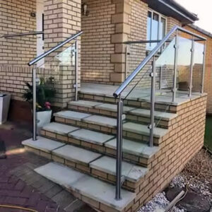
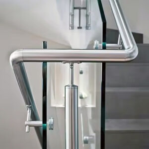
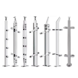
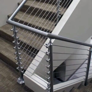
Pier and dock railings sit at the boundary between a structure and open water, which means post lines, infill panels, and mounting zones all have to answer to edge conditions that shift along the run — a straight deck section behaves differently from a ramp transition, a gate opening, or a corner. Before a layout drawing can be divided into modules, the site geometry and intended use of each zone have to be fixed. Getting this sequence wrong does not just create a cosmetic mismatch; it can force field changes to posts, infill, or mounting hardware after fabrication has already started.
Site geometry that must be settled before dividing the railing into modules
A railing run on a pier or dock is rarely a single uninterrupted length. It is a series of conditions — deck edges that may not be straight or level, construction joints, ramps, gates, corners, and zones reserved for service access — that each impose a constraint on where a post can sit and how wide an infill module can be. The order in which these are resolved matters because every later layout decision depends on them. If module widths are set first and site geometry is confirmed afterward, the layout has to be redrawn around conditions that should have driven it from the start.
The underlying mechanism is straightforward: a post line is a response to verified geometry, not an assumption about it. Where the deck edge is a straight, continuous surface with no interruptions, a post line can be set at a constant offset and the infill divided with few exceptions. Where the edge changes direction, steps down, or is interrupted by a gate or a service zone, the post line has to be evaluated separately at each of those points before any module spacing is assigned. Treating the whole run as uniform before these conditions are located produces a layout that looks complete on paper but does not match the site once posts are set.
This is why site geometry is treated as a distinct step rather than folded into general layout drafting. A ramp transition changes the plane the railing sits in, which affects post height and infill geometry independently of module width. A joint in the deck structure may define where a post cannot be placed, regardless of where the module spacing would otherwise put it. A gate opening fixes two post locations that the rest of the run then has to be divided around, rather than the gate being fit into a pre-set module grid. Service-access zones reserve a length of the run where posts or mounting hardware cannot be placed at all, which again has to be known before spacing is proposed.
The practical consequence for the buyer is that a layout package cannot be produced from a dimensioned drawing alone. It requires confirmation that each of these site conditions has been physically verified — not assumed from design drawings — because pier and dock structures are prone to as-built variation from the original plan. Where verified conditions differ from what a design drawing shows, the post line follows the verified condition.
Post lines around deck edges, joints, ramps, gates, and corners
| Site condition | Information to verify | Post-line decision to show |
|---|---|---|
| Deck edges | Verified deck-edge location | Position of the post line in relation to the edge |
| Joints | Verified joint locations along the run | Relationship between each joint and the post line |
| Steps and ramps | Locations of steps, ramps, and their transitions | Post-line path through each change in the run |
| Gates | Location and width of each gate opening | Post-line termination on each side of the opening |
| Corners | Location and local condition of each corner | Where the post line turns or ends |
| Service-access zones | Location and extent of each reserved access zone | Post-line boundary around the access zone |
Once the governing site conditions are identified, the post line itself becomes the organizing reference for the rest of the layout. A post line is not simply a dimension offset from the deck edge; it is a path that has to respond individually to each condition along the run while remaining structurally and visually coherent as a whole.
The judgment changes with the condition. At a plain deck edge with no interruption, the post line can follow a fixed offset relationship to that edge, and the remaining layout decisions are primarily about dividing the span between posts. At a joint, the post line’s relationship to that joint has to be shown explicitly, because joints can indicate a structural transition, a movement allowance, or a change in substrate — any of which can affect where a post may be anchored. At a step or ramp, the post line has to track the change in plane through the transition rather than being drawn as if the deck were a single flat surface; the posts before, within, and after the transition may need different heights or base conditions to keep the top rail consistent.
Gates introduce a different kind of constraint: the post line does not merely pass through a gate location, it terminates on each side of the opening, and those termination points fix the gate width and the hardware interface independently of how the rest of the run is divided. Corners are similar in that the post line changes direction rather than simply continuing, and the local condition at that corner — its angle, its structural support, whether it coincides with another constraint such as a joint — determines where the turn is made.
Service-access zones require the post line to respect a boundary rather than a point condition. The post line has to route around the entire reserved zone, which can mean a longer unsupported span on one side or a deliberate offset that keeps the zone clear for its intended use.
Because pier and dock structures carry corrosion and movement considerations that differ from typical building envelopes, the post line decisions above also intersect with material and finish questions addressed in pier dock railing systems 和 滨水区栏杆解决方案 contexts, where the surrounding environment has already shaped which stainless steel grades and finishes are under consideration. The post line itself, however, is a geometry decision first; material selection does not change where a joint, ramp, or gate requires the line to respond.
Infill widths and end conditions for glass, cable, or picket layouts
| Layout decision | Geometry to use | 决策边界 |
|---|---|---|
| Module width between posts | Verified faces of the posts that bound the module | Coordinate the glass, cable, or picket module with the actual post-face spacing |
| Module at a corner | Corner condition and the faces of the adjoining posts | Set the corner module from its local geometry |
| Module across changing geometry | Post faces and corner conditions for each part of the run | Divide the run locally rather than forcing equal modules across the change |
| Infill end condition | Bounding post face and the applicable end or corner condition | Show how the selected glass, cable, or picket layout terminates at that location |
Once post lines are fixed, infill module widths follow from the actual spacing between post faces — not from a target panel width imposed uniformly across the run. This distinction matters because glass, cable, and picket infill each have different tolerances for irregular module widths, and each responds differently when a corner or end condition forces an odd-width panel.
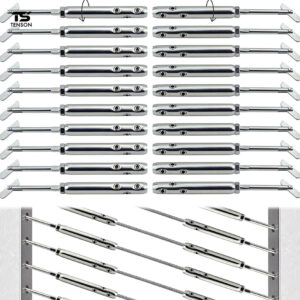
Glass infill modules are generally least forgiving of forced uniformity, because a glass panel’s width is fixed at fabrication and cannot be field-adjusted the way a cable run or picket spacing sometimes can. Where post faces define a non-standard width — at a corner, near a gate, or at the end of a run against a fixed structure — the glass module has to be sized to that specific opening rather than trimmed from a standard panel after the fact. Cable infill offers more flexibility at intermediate spans, since cable spacing can often be adjusted slightly, but corner and end conditions still fix the geometry the end fittings must accommodate. Picket infill sits between the two: individual picket spacing can usually absorb minor width variation, but the end pickets at a post or corner still have to resolve against that post’s actual face.
The decision boundary in every case is the same: module geometry is derived locally, from the post faces and corner condition at that specific location, rather than from a global average applied across a changing run. Forcing equal panel widths across a run that includes a corner, a ramp transition, or a gate produces either an oversized gap at the irregular location or a module that does not fit the opening it is meant to fill.
End conditions compound this. Where an infill run terminates against a wall, a fixed structure, or a change in railing type, the last module has to be detailed against that specific boundary condition, including how the selected infill type (glass clamp, cable terminal, or picket connection) interfaces with whatever it abuts. A termination detail that works against a post does not necessarily work against a wall or a structural column, because the fastening geometry and the clearance available differ.
For projects combining infill types along one run — glass at a scenic section, picket elsewhere — each transition point becomes its own end condition requiring resolution, rather than an incidental seam between two otherwise independent layouts.
Mounting zones, substrates, edge conditions, and underside access
| Project input | What the layout package should identify | Review decision |
|---|---|---|
| Mounting approach | Whether the proposed fixing zone is top-mount, fascia, or another project-specific arrangement | Which fixing zone is being reviewed at that location |
| 基质 | Substrate associated with each proposed fixing zone | Whether the fixing zone and substrate have been coordinated |
| Edge condition | Verified edge condition beside each proposed fixing zone | Whether the zone is located in relation to the actual edge |
| 防水 | Waterproofing information at each proposed fixing zone | Whether the mounting interface can be reviewed with the waterproofing context shown |
| Underside access | Whether the underside of each proposed fixing zone is accessible | Whether the proposed zone relies on access that the project can provide |
Mounting zone selection determines how loads from the railing transfer into the structure, and that decision cannot be separated from what the structure actually offers at each location along the run. Two mounting approaches commonly appear in this context — top-mount, where the post base sits on and fastens into the top surface of the deck, and fascia mount, where the post is fixed to the vertical face of the deck edge rather than its top surface — and the choice between them is driven by what the substrate and edge condition will support, not by a uniform preference applied across the whole run.
The mechanism here is that a mounting approach assumes a particular substrate capacity and edge geometry. Where the deck edge has sufficient depth and a substrate capable of accepting top-mount fasteners with adequate edge distance, top-mount is a viable option. Where the edge is narrow, where the top surface finish or structure cannot accommodate a top-mount base without compromising edge distance, or where a fascia condition is specifically intended to keep the top surface clear, fascia mounting becomes the relevant alternative. Neither approach is inherently correct; each depends on the edge and substrate condition at that specific point in the run, which is why a single project can reasonably use different mounting approaches at different locations if the conditions differ.
Waterproofing interacts with this choice directly. A mounting zone penetrates the deck surface or its edge, and how that penetration is sealed depends on the waterproofing system already in place or planned for that location. A mounting detail proposed without reference to the waterproofing context risks compromising the water management the deck structure depends on, particularly in a pier or dock environment where the structure is continuously exposed to moisture and spray.
Underside access is a related but separate condition: some mounting approaches, particularly those requiring blind fasteners or backing plates, depend on access to the underside of the deck at the fixing zone during installation or later maintenance. Where that underside is enclosed, finished, or otherwise inaccessible, a mounting approach that assumes underside access is not viable regardless of how well it suits the substrate and edge condition. Reference frameworks such as UFGS 05 52 00 Metal Railings illustrate how a metal-railing specification can organize mounting, substrate, and submittal information into a structured format; the structure is illustrative only, not a requirement that applies to this project or to ESANG’s products.
Access paths for circulation, maintenance, replacement, and dock equipment
| Access purpose | Area or components to keep reachable | Conflict to check on the layout |
|---|---|---|
| Circulation | The planned circulation path beside or through the railing run | Whether the path overlaps access needed at terminals, clamps, fasteners, or drainage points |
| 维护 | Terminals, clamps, fasteners, and drainage points | Whether circulation or dock equipment blocks maintenance reach |
| Replacement | Terminals, clamps, fasteners, and drainage points that may need replacement access | Whether circulation or dock equipment blocks the required access path |
| Dock equipment | The dock-equipment zone beside the railing run | Whether equipment occupies access around terminals, clamps, fasteners, or drainage points |
A pier or dock railing layout has to coexist with how people and equipment move through the same space over the life of the installation, not only at the moment of handover. Circulation paths, maintenance reach, replacement access, and dock equipment zones each place a different kind of demand on the same physical area around the railing, and those demands can conflict with one another if the layout does not account for all of them together.
Circulation is the most immediate condition: a path intended for regular foot traffic or equipment movement has to remain clear, but it also has to be checked against where maintenance or replacement access is needed at terminals, clamps, fasteners, and drainage points. Where a circulation path runs directly alongside a terminal or clamp location, routine traffic can make that point difficult to reach when service is needed, even though the path itself was never intended to obstruct the railing.
Maintenance and replacement access differ from circulation in what they require: not a clear path for movement, but sufficient clearance and reach at specific component locations to carry out inspection, tightening, or part replacement. Terminals, clamps, fasteners, and drainage points are the locations where this matters most, because they are the points most likely to require attention over time and the points where restricted access turns a routine task into a more involved one. A layout that places these components hard against a fixed obstruction, or in a location only reachable by disrupting an active circulation path, has not resolved this condition even if the structural layout is otherwise sound.
Dock equipment introduces a zone-based conflict rather than a point-based one. Where equipment is stored, operated, or moved through an area immediately adjacent to the railing run, that equipment’s working envelope can overlap with the same terminals, clamps, or drainage points that need periodic access. The conflict is not that the equipment damages the railing in the course of normal use, but that its presence can make a maintenance or replacement location temporarily or permanently difficult to reach.
Resolving these conditions means checking the layout for overlap in both directions: whether planned circulation or equipment zones intrude on known service points, and whether service points have been placed with enough clearance to remain reachable regardless of how the surrounding space is used. Where mounting method has already been decided, this access requirement also connects to how posts are fixed — a comparison addressed in the post mounting method comparison for stainless steel glass and cable railings — since some mounting and fixing arrangements require more sustained access for inspection or adjustment than others.
Layout package for supplier drawings and project review
By the time post lines, infill modules, mounting zones, and access paths have been resolved, the layout package functions as the single reference that carries all of those decisions into supplier drawings and project review. Its purpose is not to introduce new information but to represent, in a coordinated form, the conditions and decisions already established at each stage.
What the package needs to show is governed by what each earlier decision depended on. The post line requires the verified deck edges, joints, steps, ramps, gates, corners, and service-access zones to be shown alongside the post positions themselves, so a reviewer can confirm the post line responds to actual conditions rather than an assumed uniform edge. The infill layout requires the post faces and corner conditions to be visible at each module, so a reviewer can check that module widths and end conditions were derived locally rather than forced into equal panels. The mounting zones require substrate, edge condition, and waterproofing context to be shown at each fixing location, together with whether underside access is available, so a reviewer can confirm the proposed mounting approach is actually supportable at that point. The access paths require circulation routes and dock equipment zones to be shown in relation to terminal, clamp, fastener, and drainage locations, so conflicts can be identified before installation rather than after.
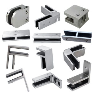
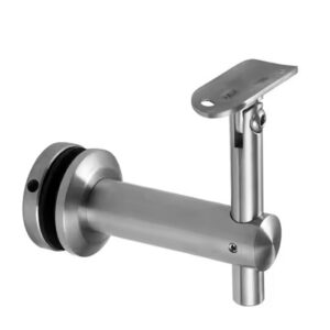
This is the stage at which the information a project team supplies — verified site measurements, substrate and waterproofing details, access and equipment zone locations — enters a supplier’s configuration and quotation review, since hardware selection, sizing, and finish for glass clamps, spigots, handrail brackets, or other fittings can only be matched to a layout once these conditions are represented accurately. A layout package built without this coordination forces the supplier to make assumptions about geometry, substrate, or access that the project team is better positioned to confirm directly.
Where all four categories of decision are represented with their governing conditions attached, the package supports a structured review against a reference format such as UFGS 05 52 00 Metal Railings, without claiming that format as a code requirement, and against the general corrosion-environment context described in ISO 9223:2012, without that standard selecting a specific grade or predicting a service life for the installed railing. What the project still needs to confirm is whether every condition shown on the layout reflects current site measurements rather than design-stage assumptions, since pier and dock structures can shift between design and installation in ways that change post lines, mounting substrates, or access clearances already drawn.
常见问题
问: Can infill module sizes be finalized before the pier or dock geometry is verified?
A: Final module sizes should follow verified post faces, edges, joints, transitions, gates, and corners. If any of those conditions are still provisional, identify them as items to confirm and delay the affected module dimensions; otherwise, a small site change can force new end conditions or a wider layout revision.
问: Should every glass, cable, or picket module be the same width for a more regular appearance?
A: Equal modules are useful only where the verified geometry supports them. At corners, gates, ramps, or changing deck edges, prioritize a workable local termination and clearly show any unequal module; if visual symmetry is a project priority, flag that priority before supplier drawings so it can be weighed against the actual post locations.
问: What should the project team do if underside access will not be available at a proposed mounting location?
A: Treat the missing access as a mounting constraint before confirming that location. Mark where access is unavailable, together with the substrate, edge, and waterproofing context, then have the responsible project parties review whether the fixing zone or mounting approach must change rather than assuming the proposed detail can be installed and serviced.
问: How can dock equipment be checked against railing access needs before approval?
A: Overlay the equipment zone and normal circulation route on the railing plan, then trace the access needed to reach terminals, clamps, fasteners, and drainage points for maintenance or replacement. Resolve any overlap by adjusting the reserved access boundary, equipment position, or railing layout before those positions become fixed in supplier drawings.
问: What should be identified as unverified when the layout package is issued for review?
A: Distinguish confirmed site information from field items still to be checked, especially deck edges, joints, gate openings, corner conditions, substrates, waterproofing interfaces, and underside access. This lets reviewers approve settled areas while directing surveys or coordination to the exact locations that could still change post, infill, or mounting decisions.