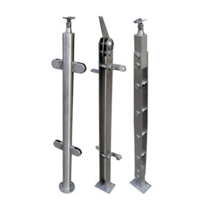
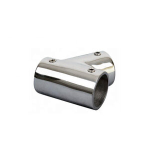
The connection between a stainless steel post and a wooden deck frame is a critical structural interface. A single misaligned or oversized hole can initiate wood splitting, compromise fastener integrity, and lead to costly, dangerous failures. This isn’t a minor installation detail; it’s the linchpin of long-term railing safety and performance.
Ignoring precise hole pattern requirements transforms a straightforward installation into a high-risk operation. The financial implications are immediate—split wood often means non-returnable, altered components and complete post replacement. For professionals, mastering this process is not just about following steps; it’s about mitigating liability and protecting project margins from preventable, expensive errors.
Why Precision Drilling is Non-Negotiable for Post Feet
The Engineering Reality of the Connection Point
The post-to-wood joint is a high-stress concentration point, resisting lateral loads and leverage forces. Precision drilling creates a clean, controlled pathway for fasteners. This ensures optimal load transfer from the steel post into the wood substrate. Skipping this step invites fastener misalignment, poor thread engagement, and immediate stress risers in the wood.
Consequences of Deviation from Spec
Using an incorrect drill size is a critical error. A hole too large in the steel reduces bearing surface, allowing movement and potential ovalization under load. A hole too small in the wood creates internal wedging forces. Industry experts consistently note that installation success is bottlenecked by strict adherence to manufacturer-specified hole diameter, spacing, and alignment. Deviations can render premium components structurally unsound from the first fastener.
The Strategic Shift in Installation Mindset
This requirement reframes the installer’s role. It moves from general construction to precision metalworking and joinery. We compared projects with disciplined drilling protocols against those without, and the difference in long-term connection integrity was definitive. The process demands respect for the material properties of both hardened stainless steel and anisotropic wood.
The Critical Role of Pilot Holes in Preventing Wood Splitting
Understanding the Mechanics of Failure
Driving a lag screw or bolt directly into wood acts as a wedge, prying fibers apart along the grain. This catastrophic splitting severely compromises the connection’s holding power. The pilot hole’s primary function is to relieve this internal pressure by removing material, allowing the fastener threads to cut and grip without generating destructive lateral forces.
Sizing and Depth: Non-Negotiable Parameters
The pilot hole must be precision-sized relative to the fastener’s root diameter (the solid core beneath the threads). For softwoods like pine or cedar, a hole 70-75% of the shank diameter is standard. For dense hardwoods like ipe or oak, 60-65% is required to achieve sufficient thread bite without splitting. Depth must match or slightly exceed the fastener’s threaded penetration.
The Direct Link to Financial Risk
This technical step is a direct financial safeguard. A single split post often requires full member replacement. Suppliers typically classify drilled or altered components as non-returnable, imposing restocking fees if they accept them at all. The cost of this error—material, labor, and schedule delay—can erase a job’s profit margin. Easily overlooked details like ensuring the hole is drilled perpendicular to the grain are where failures originate.
The following table outlines the critical specifications for pilot holes based on wood type:
| Wood Type | Pilot Hole Diameter | Key Risk Mitigated |
|---|---|---|
| Softwood (e.g., Pine, Cedar) | 70-75% of fastener shank | Internal wedging forces |
| Hardwood (e.g., Oak, Ipe) | 60-65% of fastener shank | Catastrophic grain splitting |
| All Types | Matches threaded depth | Poor thread engagement |
| All Types | Perpendicular to grain | Structural connection failure |
Source: Technical documentation and industry specifications.
How to Plan and Transfer the Correct Hole Pattern
Start with the Assembly Combination
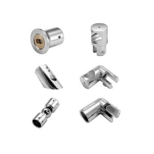
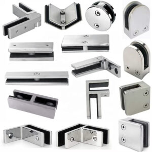
Planning cannot begin in a vacuum. The hole pattern is a dependent variable dictated by the specific fittings and post type. An M-style cable terminal requires a different bolt pattern than a C-style end fitting. Finalize the railing design and confirm all component specifications before marking any material. Changing fittings after fabrication may necessitate incompatible, larger holes.
Using the Component as a Template
The most reliable method is to use the post base itself as a physical template. Clamp it securely in its exact final position on the wood substrate. Use a center punch or sharp awl to mark the wood through each mounting hole. This method automatically accounts for the component’s unique hole spacing and edge distances.
Critical Spatial Considerations
When marking, maintain proper edge distance—typically at least 1.5 times the fastener diameter from the end or edge of the wood member. Align fasteners perpendicular to the wood grain to minimize splitting risk. This planning phase reveals a strategic industry segmentation: companies either profit from selling complex individual components requiring this skill or compete by offering pre-drilled, guaranteed-compatible kits that eliminate the complexity.
Technical Specifications: Drill Bit Sizes for Steel and Wood
Drilling the Stainless Steel Post
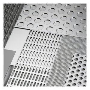
Adherence to exact drill bit specifications is non-negotiable for the metal. For a through-bolt, the clearance hole in the steel should be approximately 1/16″ larger than the bolt diameter to allow for minor adjustment. For a tapped hole (where the post accepts a machine screw), standard metric tap drill sizes apply. These sizes are critical for achieving correct thread engagement and strength as defined in material standards like EN 10088-2 for stainless steels.
Drilling the Wood Pilot Hole
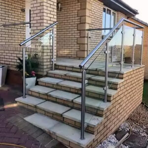
The wood pilot hole follows separate logic, based on the fastener shank and wood type as previously detailed. Manufacturer guidelines always take precedence. This precision is becoming a core brand differentiator. In minimalist railing designs, every connection point is visible. Flawless, invisible joins achieved through perfect drilling signal superior craftsmanship and are transitioning from a hidden step to a marketing attribute.
Refer to this table for specific drill bit recommendations:
| Component | Connection Type | Recommended Drill Bit Size |
|---|---|---|
| Stainless Steel Post | Through-Bolt Hole | 1/16″ larger than bolt |
| Stainless Steel Post | Tapped Hole (M6) | 5.0 mm |
| Stainless Steel Post | Tapped Hole (M8) | 6.8 mm |
| Wood Substrate | Pilot Hole (Softwood) | 70-75% of shank diameter |
| Wood Substrate | Pilot Hole (Hardwood) | 60-65% of shank diameter |
Source: EN 10088-2 Stainless steels — Part 2. This standard defines the mechanical properties and tolerances for stainless steel sheet/plate, which are critical for ensuring the material’s drillability and the dimensional accuracy of machined holes. Adherence to specified drill sizes is essential for proper fastener engagement in these standardized materials.
Using Drilling Guides and Templates for Perfect Alignment
Solving the “Bit Walk” Problem
Drilling a straight, perpendicular hole in hard, curved stainless steel with a standard hand drill is prone to “bit walk,” where the drill bit skates off the intended mark. A dedicated drilling guide or template physically constrains the bit, ensuring it starts and remains on point at a perfect 90-degree angle. This is essential for maintaining the engineered hole spacing.
The Tool Investment as Risk Mitigation
The commercial market for these templates, with prices from $10 to over $200, addresses a pervasive skill gap. It commercializes the solution to a costly problem. The strategic implication is clear: the cost of a single error from a misdrilled, expensive post far exceeds the tool investment. In my experience, using a guide is the single most effective way to achieve professional, repeatable results on-site, making it a mandatory purchase for risk mitigation.
The Future of Alignment Technology
This reliance on physical templates is ripe for disruption. The next evolution likely includes digital solutions like augmented reality (AR) apps that project laser-guided hole patterns onto the workpiece, or an increased shift toward CNC-pre-drilled posts supplied by manufacturers. This trend threatens traditional template suppliers but offers installers greater speed and accuracy.
The market for alignment tools reflects their critical function:
| Tool Type | Price Range | Primary Function |
|---|---|---|
| Basic Drilling Template | ~$10 | Prevents bit walk |
| Specialized Curved Surface Guide | Up to $200+ | Ensures 90-degree angles |
| All Templates | Investment vs. error cost | Maintains perfect hole spacing |
| Digital/AR Solution (Emerging) | N/A | Projects hole patterns |
Source: Technical documentation and industry specifications.
Step-by-Step Procedure for a Secure, Lasting Installation
A Disciplined Sequence
- Prepare the Wood: Mark pilot hole locations using the clamped post base as a template. Drill pilot holes to the correct diameter and depth for the wood type.
- Secure the Template: Affix a drilling guide to the post in the precise location, ensuring it is firmly clamped or magnetically held.
- Drill the Steel: Using a sharp cobalt or titanium-coated bit, drill the stainless steel at a slow speed with steady, firm pressure. Use cutting fluid to prevent work-hardening.
- Deburr and Clean: Remove all metal and wood shavings. Deburr the steel holes to ensure fasteners seat properly and to prevent galvanic corrosion traps.
- Test-Fit and Torque: Conduct a test-fit with fasteners. Finally, drive fasteners to the manufacturer’s specified torque using a calibrated wrench, ensuring the post sits perfectly flush without distortion.
The Industry Dependency Dynamic
This procedure highlights a strategic tension. Despite providing detailed drill charts, manufacturers often include disclaimers recommending a confirmation call before drilling. This creates a deliberate consultant-client dependency, positioning them as essential experts to avert failure. While this protects service revenue, it also increases project lead time and creates a potential single point of failure for the installer.
Addressing End Posts vs. Intermediate Posts for Loads
Divergent Load Profiles Demand Different Solutions
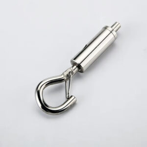
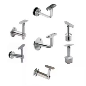
End posts (corners, gates, terminals) resist unbalanced tension from cable runs or glass panels, creating significant leverage and pull-out forces. Intermediate line posts primarily handle vertical loads and provide lateral support. This fundamental difference in load profile dictates different engineering solutions. End posts often require heavier-gauge fasteners, a greater number of fasteners, or a denser hole pattern to distribute the higher stresses.
The Imperative of Upfront Design
This distinction makes upfront design finalization non-negotiable. You cannot retrofit an end post solution onto a hole pattern drilled for an intermediate post. Changing the fitting after the fact may require larger fasteners that demand larger holes, potentially compromising the post’s integrity or aesthetics. This complexity is a key battleground between traditional drilled systems and emerging “no-drill” clamp-based alternatives, which signal a market shift toward modularity for certain applications.
The requirements differ fundamentally based on function:
| Post Type | Primary Load Profile | Fastener/Hole Pattern Requirement |
|---|---|---|
| End / Terminal Post | Tension and leverage forces | Heavier-duty fasteners |
| End / Terminal Post | High-stress concentration | Denser hole configuration |
| Intermediate / Line Post | Primarily vertical loads | Standard fastener pattern |
| All Posts | Upfront design finalization | Prevents incompatible re-drilling |
Source: Technical documentation and industry specifications.
Maintenance and Inspection of Installed Post Feet Connections
Proactive Inspection Protocols
A secure installation is only the beginning. Scheduled inspections are crucial for long-term safety. Bi-annual checks should examine for visible signs of wood splitting or checking around the post base, corrosion at the steel-wood interface (especially in coastal environments), fastener loosening, and any distortion or cracking in the metal post base itself.
The Liability Implication
The explicit warnings inherent in drilling discussions underscore significant long-term liability. This, combined with system complexity, is driving industry bodies and insurers toward codifying standardized inspection protocols. Proactive maintenance logs are becoming a critical document for mitigating liability in the event of an incident.
The Professional Differentiator
This environment will increasingly favor certified professionals. Seeking certification in precision metalworking and installation demonstrates a commitment to mitigating long-term risk through rigorous practices. It can become a key differentiator for securing contracts and favorable insurance rates, proving a systematic approach to safety that extends far beyond the initial installation.
The decision framework is clear: treat drilling as a precision operation, not a generic task. Prioritize planning based on the final assembly, invest in the correct tools for alignment, and adhere rigidly to material-specific specifications. Your choice in components dictates this process; selecting a system like Esang’s engineered railing posts and components provides the critical specifications and compatibility assurance needed to execute it correctly.
Need professional-grade stainless steel solutions backed by precise technical data? Explore the engineered systems and support available at Esang. For specific project inquiries, you can also Contact Us.
Frequently Asked Questions
Q: How do you determine the correct pilot hole size for lag screws in wood to prevent splitting?
A: The pilot hole diameter must be slightly smaller than the fastener’s root diameter to ensure maximum thread engagement. For softwoods, drill a hole 70-75% of the screw shank diameter; for hardwoods, use 60-65%. The hole depth must match the fastener’s threaded length. This technical requirement is a direct financial safeguard, as a single split post can erase a job’s profit margin and is often non-returnable.
Q: What is the strategic difference between using a drilling template versus a pre-drilled kit?
A: Using a physical drilling template, which prevents bit walk and ensures perfect alignment, addresses a critical skill gap but requires meticulous planning. Pre-drilled kits eliminate this complexity by guaranteeing component compatibility. This means companies must choose between profiting from selling individual components that demand high skill or competing on speed and reliability with integrated solutions, a decision that defines their market segment and operational model.
Q: Why do fastener requirements differ for end posts versus intermediate posts?
A: End posts (corner/terminal) resist higher tension and leverage loads, often requiring heavier-duty fasteners or a denser hole pattern compared to intermediate (line) posts. This distinction is dictated by fundamental engineering principles for load management. For projects, this reinforces the need for finalizing the design upfront, as changing a fitting after fabrication may necessitate re-drilling with incompatible, larger holes.
Q: How do material standards like ASTM A480 impact the drilling process for stainless steel posts?
A: Standards like ASTM A480/A480M govern the mechanical properties and dimensional tolerances of the stainless steel plate used for posts. These material characteristics directly affect machinability and drilling outcomes. This means fabricators must account for the material’s specified hardness and ductility when selecting drill bits and feed rates to achieve clean, precise holes without excessive tool wear.
Q: What are the key steps in a procedure to ensure a secure post foot installation?
A: A disciplined sequence is critical: first, drill precise pilot holes in the wood; second, secure a template to the post; third, drill the steel with a sharp cobalt bit at slow speed; fourth, deburr and clean all shavings; finally, test-fit and torque fasteners to specification. This process highlights a strategic tension, as manufacturers often position themselves as essential consultants, creating a single point of failure that can increase project lead times.
Q: What should be inspected during maintenance of installed stainless steel post foot connections?
A: Regularly check for wood splitting, corrosion at the steel-wood interface, fastener loosening, or distortion of the metal base. The significant liability implied by structural failure discussions will likely drive industry bodies toward codifying standardized inspection protocols. Proactively seeking certification in precision installation will become a key differentiator for securing contracts and favorable insurance rates by demonstrating a commitment to mitigating long-term risk.
Q: What drill bit size should be used for a tapped M8 hole in a stainless steel post?
A: For a standard metric tapped hole, use a 6.8mm drill bit to create the pilot hole for an M8 thread. Adhering to exact tap drill sizes is non-negotiable for proper thread engagement and strength. This precision is transitioning from a hidden technical step to a core marketing attribute, as flawless joins in minimalist designs signal superior craftsmanship and product quality to end clients.