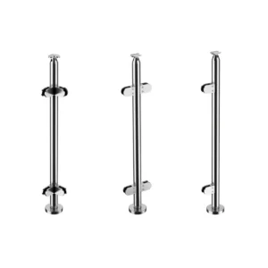
Use a Longer Spacer Body Without Treating Length as Unlimited
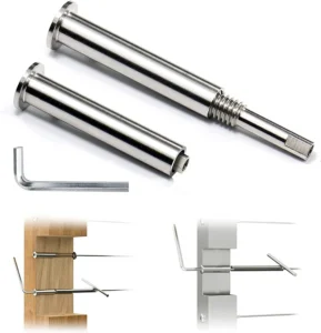
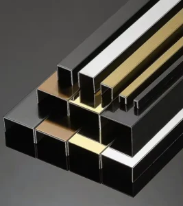
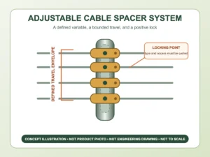
Extended-length cable spacers are longer intermediate members for layouts that need a greater finished spacer height, additional cable rows, or a longer distance between the spacer’s top and bottom receiving interfaces. In this context, “extended length” describes the spacer body. It does not automatically permit a wider post-to-post bay, replace structural posts, or increase the railing system’s approved capacity.
As a spacer becomes longer, section size, wall thickness where applicable, perforations, end restraint, handling, and transport have a greater influence on visible bow, twist, and installation stability. The useful request is therefore not “make it as long as possible,” but “review this defined length and cable schedule against these two support interfaces.”

Define Which Dimension Is Extended
Use a marked elevation to distinguish four dimensions that are often confused:
- overall spacer length: the physical end-to-end body dimension;
- installed clear height: the distance between the finished top and bottom receiving interfaces;
- cable pattern length: the distance from the first to the last cable centerline; and
- horizontal bay span: the distance between structural posts, which is a separate system field.
An extended body may be needed because the first and last cable positions are farther apart or because brackets and end treatments occupy more length. It should not be selected merely because the horizontal bay is long. That bay still needs its own structural-post and spacer-station layout.
Review Stiffness Before Adding Rows or Length
A longer, slender member is more sensitive to handling and to side forces introduced while multiple cables are threaded and tensioned. The proposed configuration should identify the bar profile, outside dimensions, wall or solid section where relevant, usable unsupported length, number and position of openings, and how both ends are restrained.
Adding cable rows does more than extend a drilling pattern. Each opening removes material and creates another contact point. Dense rows, large openings, slots, or holes close to an end connection can change stiffness and fabrication tolerance. If an offered design uses a sleeve, liner, guide, or locally reinforced area, it should be itemized rather than inferred from the page title.
If the required length cannot be handled, shipped, kept straight, or installed as one piece, ask whether a jointed or modular proposal is feasible. Any joint location, connector, alignment feature, and visual seam must be explicit. A split part is not automatically equivalent to a continuous member.
Set the Cable Pattern from Stable Datums
Provide the cable row count, center-to-center spacing, distance from each end to the nearest cable centerline, cable diameter and construction, and the largest fitting that must pass through an opening. For a long bar, a small pitch or datum error can accumulate across many rows and leave the last cables visibly or physically out of alignment with the main posts.
Openings, sleeves, and edges
The drawing should state whether the proposed path is a plain hole, slot, removable guide, split insert, or other detail. Ask for the finished opening basis and the status of any sleeve or grommet. Confirm deburring and edge finishing for both factory and site work. Cable contact at a sharp or damaged edge can create avoidable marking and installation friction.
Also verify the remaining material between adjacent openings and between the first or last opening and an end feature. A request to enlarge the holes after the bar is made can affect guide fit, edge distance, and the stiffness that the original pattern assumed.
Separate Level, Stair, and Mixed Elevations
Long level spacers normally use one vertical reference and a repeated horizontal cable schedule. Long stair spacers must coordinate the actual pitch, the cable direction through each guide, the body orientation, and the end faces that meet the stair frame. Provide rise and run or a verified site angle, not only a catalogue description.
Where a landing changes from stair to level, do not assume one extended spacer pattern serves both sides. The transition may need separate bars, different drilling schedules, or a specifically reviewed interface. Otherwise, the first level row or final stair row can miss the adjacent post pattern, create an abrupt cable bend, or place a hole too close to an end.
Use Spacer Stations to Support the Cable Layout—Not the Top Rail
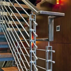
An extended spacer remains a cable-positioning member unless the project design explicitly verifies another role. Terminal posts and cable end fittings resist the cable’s termination forces. Structural intermediate posts, top rail or frame, anchorage, and their connections support the railing system. The spacer should not be used as evidence that these components or a wider bay are adequate.
The responsible project team should determine structural post spacing and the number and location of spacer stations based on the complete layout, cable tension, opening control, frame stiffness, and local requirements. If a long spacer connects to a top rail and bottom rail, those connections still need to be defined as receiving interfaces; their presence does not automatically make the spacer a structural post.
Control Cutting, Drilling, Straightness, and Shipping
Extended members make the factory/site split especially important. Ask the quotation to state:
- finished length or supplied length and permitted trim allowance;
- factory hole schedule versus field-drilled positions;
- straightness or visual acceptance basis proposed for the length;
- which end may be trimmed and how the cut is refinished;
- top and bottom brackets, plates, inserts, or caps included;
- protective packaging and bundle identification by elevation; and
- site tools, templates, assembly steps, and final inspection assigned to the installer.
Do not trim through a threaded zone, end insert, guide datum, or prepared attachment without a revised instruction. Do not field-enlarge holes simply to make an inaccurate pattern fit. Those shortcuts can turn a dimension problem into an edge, alignment, or stiffness problem.
Compare Extended Spacer Proposals on the Same Basis
| Field | Required buyer input | Quotation should state | Mismatch risk |
|---|---|---|---|
| Length | Clear height, overall target, end interfaces | Finished/supplied length, tolerance basis, trim plan | Member does not seat or loses a prepared end feature |
| Body stiffness | Unsupported length, handling and connection conditions | Profile, section, openings, end restraint, any joint | Visible bow, twist, or unstable installation |
| Cable schedule | Row count, centers, end datums, cable/fitting size | Hole/guide schedule, sleeves or inserts, edge finish | Accumulated alignment error across the long pattern |
| Route | Level, stair, landing transition, actual angle | Orientation, end cuts, drawing per elevation | Cable exits or end faces conflict with the frame |
| Scope | Exposure, requested finish, quantity, site capability | Offered material/finish; included guides, ends, brackets, fasteners, packaging | Unpriced parts, rework, or transport damage |
The product name does not confirm an infinite length range, every material, every finish, or every cable pattern. The proposed offer should identify the exact configuration. Cables, terminals, tensioners, structural posts, rails, anchors, installation, and system approval remain separate unless itemized.
Send One Elevation per Spacer Pattern
Start with a marked photo or elevation showing finished top and bottom interfaces, overall and clear dimensions, cable rows, main posts, proposed spacer stations, and any stair or landing transition. Add cable and terminal dimensions, requested material/finish, environment, quantity, site machining capability, and packaging constraints.
Before fabrication, freeze the body profile and length, stiffness-related section fields, hole/guide schedule, edge treatment, end connections, factory/site work, included components, quantity, and drawing revision. That bounded record is more useful than an open-ended request for a “long spacer.”