Glass Spigots & Standoffs
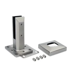
Glass Spigots & Standoffs
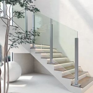
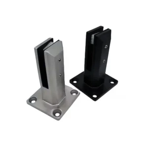
Spigots and standoffs solve two different support layouts. Spigots normally start a bottom-supported glass discussion; standoffs start a side-mounted, point-fixed discussion. Choose that load path first, then match the glass preparation, substrate, drainage or waterproofing detail and visible hardware. A photo and an approximate panel layout are enough to begin an ESANG review.
Discuss spigots or standoffs on WhatsApp
Route the project by where the glass is supported
Product route — Starting condition — Critical item to settle
Surface mount glass spigots — The glass is supported from below and the hardware sits on top of a prepared surface. — Base footprint, anchors, substrate strength, level adjustment and water management.
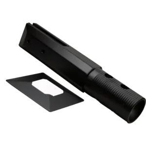
Core drill glass spigots — The bottom support enters a prepared recess or core-drilled opening. — Shank geometry, hole preparation, embedment detail, alignment and waterproofing sequence.
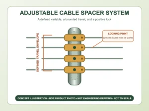
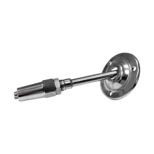
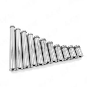
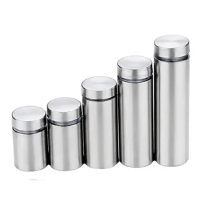
Adjustable glass standoffs — The glass is point-fixed from the side and the offset or alignment must be set within a defined range. — What adjusts, final projection, locking method and access after the glass is installed.
Mini glass standoffs — A compact visible point fixing is preferred and the project can support that hardware route. — Do not infer capacity from diameter; match the exact item to glass holes, substrate and design loads.
Heavy duty glass spigots — The project has more demanding panel, occupancy or exposure conditions requiring a reviewed support proposal. — Require the exact proposed spigot, compatible glass and substrate detail, and the basis for any performance statement.
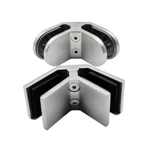
Recognize the hardware families
Coordinate the glass before ordering hardware
Bottom-supported spigot layouts
Provide panel width and height, glass build-up, the intended number and position of supports, top-edge condition and any cap rail. For surface mounting, include the base material, build-up above the structure, waterproofing and available anchor zone. For core-drill mounting, include the planned opening, depth, edge distances and the order in which the opening, membrane, spigot and finish are installed. The hardware proposal should state the required slot or liner and any glass preparation.
Side-mounted standoff layouts
Provide the hole pattern from the glass drawing, the supporting wall, fascia or stringer construction, desired glass-to-support offset and access to the rear or anchor side. The standoff body, face cap, glass contact parts, anchor connection and support substrate form one chain. A correct-looking face cap does not resolve an unsuitable anchor or misplaced glass hole.
When a different category is the better route
Choose a base shoe system when the design calls for continuous bottom support. Use glass clamps when glass connects to posts or supports through discrete clamp bodies. Use brackets and adapters for a special wall, post or transition interface. These routes may look similar at one fixing point, but they create different glass preparation, load paths and installation work.
Ask each quotation to define the boundary
• Exact spigot or standoff form, quantity and identification photo or drawing.
• Glass build-up, panel dimensions, holes and edge conditions used for the proposal.
• Mounting surface, support build-up and the assumed anchor or embedment arrangement.
• Included liners, caps, covers, fasteners and adjustment parts; structural anchors should be explicit.
• Material and finish proposed for the stated indoor, outdoor, poolside, coastal or other exposure.
• Required performance documentation, inspection points, packaging and marking.
Start with a sketch, photo or take-off
Send whichever information is available now: a panel schedule, site photo, mounting-surface sketch, estimated quantity or desired hardware appearance. ESANG’s proposed configuration should make the missing glass, anchor and installation details visible before release. Final suitability still depends on the complete installed glass system and the project team’s verified substrate and design requirements.
Related Posts:
Handrail Tube Only or a Complete Component Package: What Should the Supplier Quote Include?
Compare tube-only and component-package handrail quotes by separating fittings, fabrication, mounting interfaces, finish work and delivered quantities.
Continuous or Sectional Handrail Supply: Which Split Strategy Fits Transport and Site Assembly?
Compare continuous and sectional handrail supply using delivery access, joint locations, mating details and section identification before fabrication release.
Where Should a Handrail Change from Wall-Supported to Post-Supported Along a Mixed Route?
Choose a handrail support change by comparing wall and post interfaces, preserving the gripping path and locating the transition on coordinated drawings.
Level, Raked or Raked-to-Level Mesh Panels: Which Geometry Belongs on Each Railing Run?
Choose between level, raked, and raked-to-level mesh panel geometry by railing run, pattern orientation, interfaces, and project drawings.
How to Specify Internal Sleeves and Splice Locks for Handrail Tubes
Specify handrail sleeves and splice locks by the actual tube interior, required retention and installation access so the connector can fit and be secured.
Where Should Handrail Splices and Supports Go on Long Runs?
Locate splices with supports, transitions and assembly access so shipping breaks also work as documented connections in the installed handrail.
Esang's Projects

Esang's Certificate
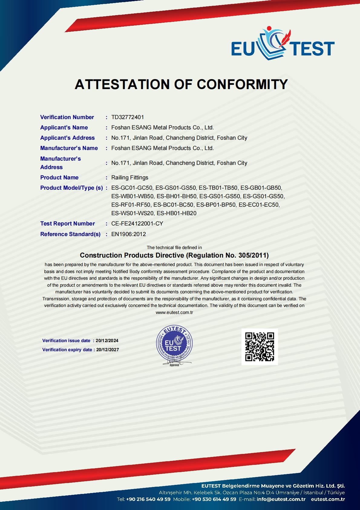
Foshan ESANG Metal Products proudly maintains CE certification (Verification No. TD32772401) under the Construction Products Directive (Regulation No. 305/2011), affirming our commitment to the highest European safety and quality standards.
Certified Product Range:
Our comprehensive railing fittings portfolio—including glass clamps, tensioners, brackets, wall mounts, base shoes, handrail fittings, cable hardware, and post components—meets EN1906:2012 standards, ensuring structural integrity and performance reliability across all installations.
What This Means for Your Project:
✓ Full regulatory compliance for European and international markets
✓ Independently verified safety and durability performance
✓ Documentation support for architectural specifications
✓ Peace of mind from third-party quality assurance
Certification valid through 2027 | Test Report: CE-FE24122001-CY
Esang's Projects

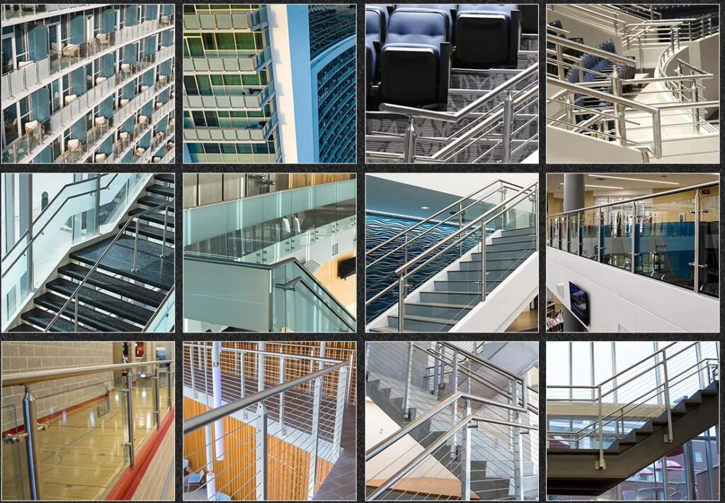
Reference Products