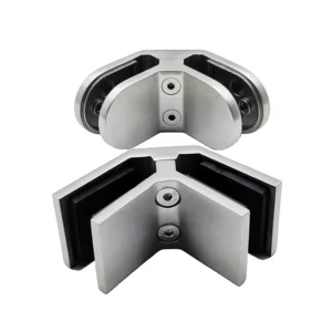
Make “135°” unambiguous on the rail layout
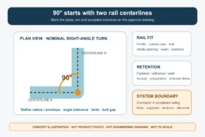
A 135 degree corner connector should be selected from a marked centerline drawing, not from the name alone. Some teams describe the included angle between two rail legs; others describe how far the route turns. A 135° included angle can therefore be discussed as a 45° change of direction. Put the angle arc on the intended side, show the travel direction and state the measurement convention.
Also define whether the connector has two rail ports or a three-port branch, whether the geometry lies in one plane, and what angular tolerance the project accepts. A photo, one rail dimension and an estimated quantity can start the inquiry; the approved drawing must settle the geometry and fit before production.
Six geometry fields prevent the wrong corner
| Field | Decision | Why it matters |
|---|---|---|
| Angle convention | Included angle or direction change, with the arc drawn on the intended side | A text-only “135°” request can describe opposite-looking routes. |
| Centerline geometry | Both rail centerlines, intersection/radius and direction of travel | Outside faces do not define the same angle when profiles or offsets differ. |
| Plane | Plan, elevation or a true 3D transition, with a second view when needed | A perspective image can hide rotation or a rise between legs. |
| Port count | Two-port corner or three-port branch, with each port labelled | A branch connector is not interchangeable with a simple direction change. |
| Tolerance | Permitted angle, twist, offset and rail-end gap | The nominal name does not set the project’s acceptance range. |
| Envelope | Centerline radius, overall projection and nearby clearance | Equal angles can occupy different space and require different rail cut-back. |
Two ports and three ports are different purchasing tasks
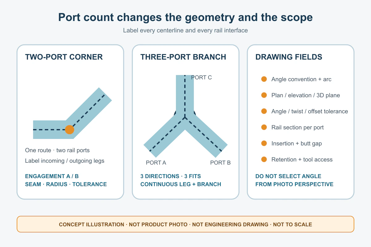
Two-port corner
A two-port connector continues one rail route through an angled change. The drawing should label the incoming and outgoing legs, engagement on each side, the visible seam and any centerline radius. If the connected rails differ, give separate section data for Port A and Port B.
Three-port branch
A three-port body adds a branch or intersection. It needs three centerline directions, a port numbering scheme and a clear statement of which rail is continuous. Do not infer the branch angle from a perspective photograph. Show plan and elevation views and identify whether all three ports use the same profile and retention.
Fixed geometry or limited adjustment
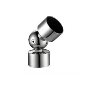
A fixed connector should be quoted to the defined angle and tolerance. If an adjustable connector is proposed, record its finite adjustment range, adjustment plane, locked final angle and locking method. “Adjustable” does not mean unlimited rotation, and it does not establish movement during service.
Fit begins with the rail section
For each port, state the rail profile, outside dimensions, wall thickness, inside opening, corner radius and internal weld-seam location. An internal spigot is controlled by the clear inside opening; an external socket is controlled by the outside profile. A nominal tube size can conceal enough variation to prevent insertion or create an unacceptable loose fit.
The proposed drawing should set insertion/overlap for every port, rail-end cuts, deburring, any holes or slots and the intended butt gap. If one leg is mitred or coped, identify whether that preparation is factory work or site work. Show finish/grain orientation so a correct angle does not arrive with an unacceptable visible transition.
Choose one retention route and define its consequences
| Retention route to request | Fields to freeze | Common scope risk |
|---|---|---|
| Set screw or through-fastener | Hole pattern, thread/fastener, access side, torque/process requirement and included hardware | Fastener access disappears after adjacent rails are installed. |
| Adhesive bond | Mating clearance, preparation, adhesive/primer, coverage, cure and temporary restraint | Adhesive or preparation is assumed but not included or suitable for the agreed joint. |
| Welded joint | Factory/site location, joint preparation, weld process, distortion control and finish restoration | A body intended for mechanical fit is treated as automatically weld-ready. |
| Combination method | Which element locates the rail, which retains it and how the assembly is inspected | Fasteners and consumables are duplicated or omitted between factory and installer. |
Locate the connector among supports and adjacent joints
Show the nearest post, bracket, splice and rail end on the layout. A 135° connector is only one component in the load path. The connected rail sections, supports, retention hardware, anchors, substrate and installation determine the completed system’s behavior. The angle name, material label or connector-body evidence cannot be promoted into a performance guarantee for the full handrail or guard.
If the project needs structural, code or environmental evidence, request documentation for the proposed port geometry, rail sections, retention and support condition. Do not transfer a value from a different connector body, angle or system.
Separate factory preparation from site setting-out
- Connector supply: geometry, ports, mating dimensions, holes/threads, proposed material/finish and identification should be explicit.
- Rail supply and preparation: list whether rails are included, cut, drilled, slotted, welded or finished; otherwise treat them as separate.
- Retention package: itemize screws, pins, inserts, adhesive or other consumables; site tools and labor remain separate unless named.
- Field work: as-built measurement, setting-out, support/anchor installation, substrate checks and final assembly need an identified owner.
- System responsibility: project engineering, completed-system performance and approval are not established by supply of the connector unless specifically scoped and evidenced.
What to send and what to expect back
Begin with the information you have:
- a plan/elevation sketch with centerlines, travel direction and the angle arc;
- included-angle or turn-angle convention, connector plane and accepted angular tolerance;
- two-port or three-port requirement and the label/function of every port;
- rail sections, wall thicknesses, inside openings and weld-seam locations;
- internal/external fit, engagement on each port, rail-end cuts and butt gaps;
- retention preference, tool access, factory/site work limits and visible finish reference;
- support locations, system role, exposure, quantity and any required evidence.
A comparable quotation should return a marked geometry drawing, mating and engagement dimensions, retention details, supplied hardware/consumables, material/finish proposal, included rail or support items, exclusions, approval point, packing and commercial terms. Do not compare a three-port prepared assembly with a body-only two-port price.
Frequently asked questions
Why is a sketch necessary if the product is called 135°?
Because the same number may refer to an included angle or a direction change, and a photo may hide the measurement plane. Centerlines, an arc and travel arrows remove that ambiguity.
Can I use a three-port connector as a two-port corner?
Do not assume so. The unused port, body geometry, retention and system role may differ. Request a configuration whose port count and load path match the layout.
Is angular tolerance included in the 135° name?
No. State the project’s permitted angle, twist, offset and gap, then have the proposal identify what it will supply and how acceptance will be checked.
Does the connector allow movement after installation?
Not unless a defined movement function, direction, displacement and locking/support arrangement are explicitly proposed and substantiated. A fixed or adjustable installation connector is normally treated as fixed in service after final locking.
Can an existing rail be matched from photos only?
Photos can start the review, but production matching normally needs measured rail sections or a sample because inside openings, wall thickness and seam clearance are not visible.
Send the angle convention first
A hand sketch with a 135° arc, two or three labelled centerlines and one measured rail size is enough to begin. The proposed configuration should then make the plane, centerline geometry, tolerance, port count, fit, engagement, retention, seam and factory/site split visible before you approve it.