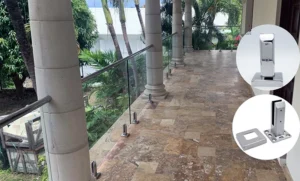
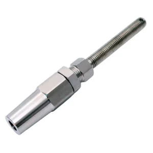
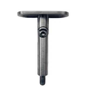
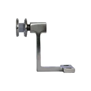
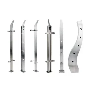
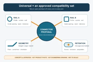
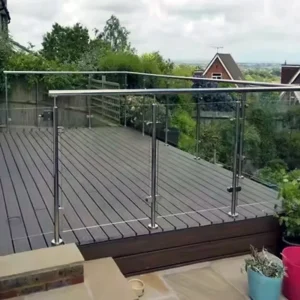
Universal surface mount systems are coordinated railing component families built around repeatable interface information: mounting surface, post and base geometry, rail or infill connection, route conditions and exposure. “Universal” does not mean one plate or bracket fits every substrate, post, infill or code requirement. ESANG can start from photos, a rough plan and estimated quantities, then prepare a project-matched component schedule for review.
Send Your Surface Mount Layout
Standardize the data before the hardware
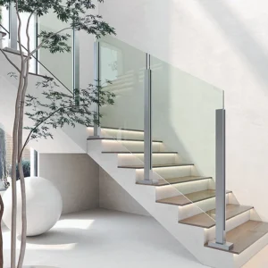
A useful universal system reduces unnecessary variation where project conditions genuinely repeat. It may use a common post section, base cover, rail connector or visual finish across several locations. The structural attachment and adjoining components still have to be checked at each distinct condition. A straight run on a broad top surface, a narrow edge, a stair landing and a glass-panel corner should not be forced into one unverified detail merely to reduce part numbers.

Five choices define the proposed family
1. Mounting surface and support below
Identify the full build-up at the post line, not only the visible finish. Timber or composite decking, concrete, structural steel, precast edges and waterproofed assemblies require different attachment decisions. Provide member thickness, edge and joint positions, access below, reinforcement or framing information, and the party responsible for anchor and waterproofing design. A decorative base cover is not a substitute for the structural or sealing detail.
2. Post and base interface
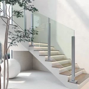
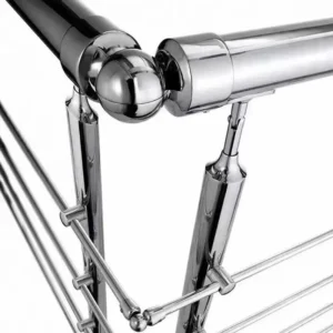
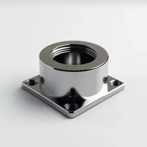
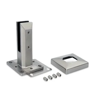
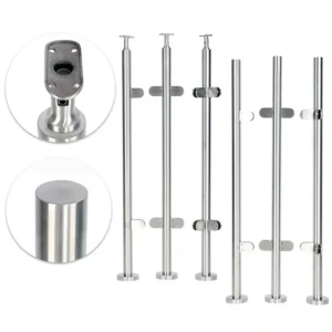
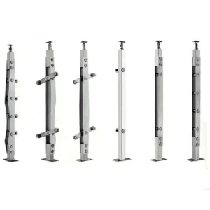
Round and square posts need matching receivers, plate openings and covers. The plate footprint and hole pattern must fit the available surface while respecting the project’s approved attachment layout. State the post section, intended height, plate orientation and whether visible fasteners are acceptable. Do not assume that two posts with the same outside dimension share the same wall thickness, insert or base connection.
3. Infill and rail family
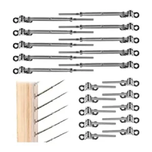
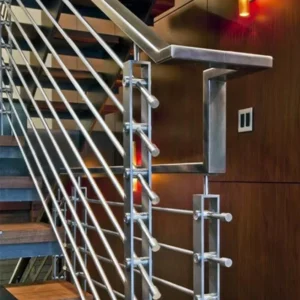
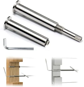
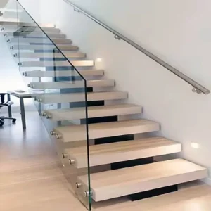
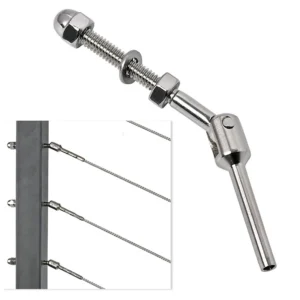
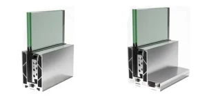
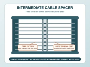
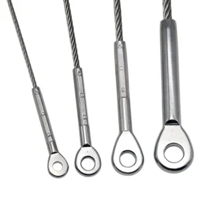
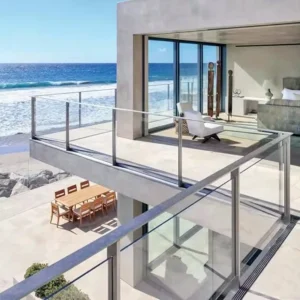
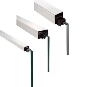
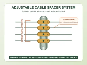
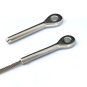
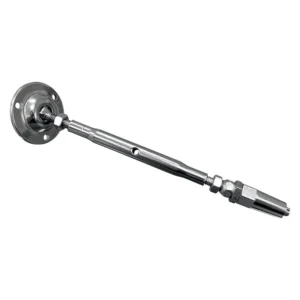
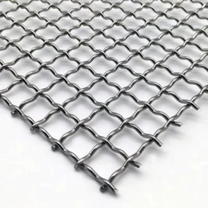
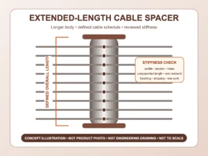
Cable, glass, picket, bar and panel infill change the post holes, terminal conditions, intermediate supports and adjoining hardware. Glass requires its panel thickness/composition and clamp or channel interface to be coordinated. Cable requires the route, terminal and tensioning arrangement to be defined. A common post appearance can still conceal different fabrication at end, corner, gate and intermediate locations.
4. Route geometry
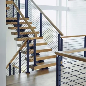
Straight level runs are the simplest place to standardize. Corners, slopes, stairs, landings, gates, changes in direction and transitions to walls or fascia create special parts and approval dimensions. Mark these conditions on the plan before quantities are grouped. A “typical post” should not be copied into a terminal or turning condition without checking the required rail and infill interfaces.
5. Exposure and finish
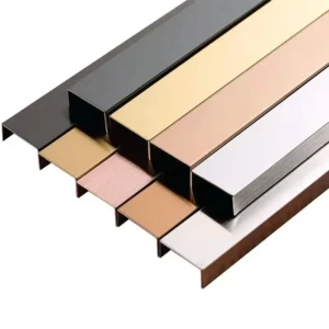
Indoor, inland exterior, coastal, poolside and industrial environments do not impose the same corrosion or cleaning duty. Give the site location, salt or chemical exposure, dissimilar materials, cleaning method and required appearance. Ask the proposal to name the material and finish for each component; do not infer grade, coating or durability from a silver or dark surface in a photograph.
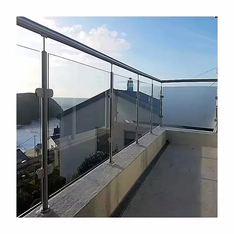
Use a schedule, not the word universal
| Location type | What may repeat | What still needs separate confirmation |
|---|---|---|
| Straight level runs | Post appearance, rail profile, finish and typical infill spacing | Mounting build-up, terminal posts, joints and attachment schedule |
| Corners and direction changes | Visible finish and selected component family | Post fabrication, rail connector, infill termination and local footprint |
| Stairs and landings | Material palette and coordinated rail family | Slope, height datum, transition pieces, post locations and base orientation |
| Glass, cable or panel variants | Post family where the interfaces permit | Infill-specific holes, clamps, terminals, tolerances and engineering inputs |
| Different substrates | Above-base visual language where practical | Base plate, anchors, support below, isolation and waterproofing |

Define the package and site responsibilities
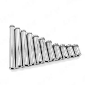
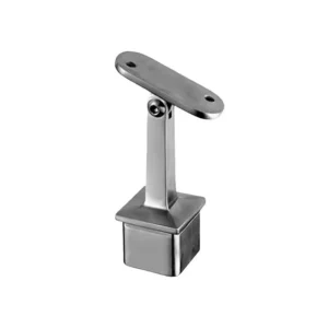
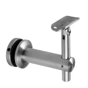
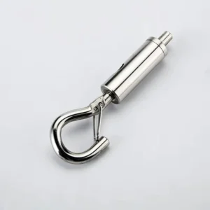
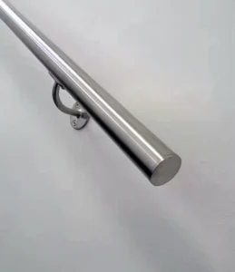
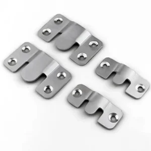
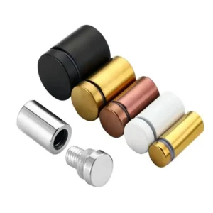
A proposed component package may include posts, base plates or receivers, decorative covers, rail supports, top or handrail sections, infill connectors, corners, joiners, end caps and associated component fasteners. The quotation should list the proposed items rather than presenting one photograph as a complete system.
Substrate investigation, blocking or reinforcement, anchor design, site drilling, concrete scanning, welding, grouting, sealants, waterproofing, glass design and final code verification should remain clearly assigned unless the written scope says otherwise. The capacity or suitability of one plate, post or fitting must not be presented as the performance of the complete installed railing.
Information needed to start a useful quotation
You can begin with photographs and approximate quantities. Add the following as the design develops:
- plan and elevations showing straight runs, corners, slopes, stairs, gates and terminations;
- sections through each different mounting surface, including support below and access;
- preferred post and rail profiles, infill type and visible finish;
- glass, cable, picket or panel information already fixed by the project;
- indoor/outdoor exposure, site location and cleaning environment;
- estimated quantities by location type and any required spares;
- required drawings, samples, material documents, packing and delivery sequence.
Ask the proposal to identify the post/base geometry, interfaces by location, material and finish, included fittings and component fasteners, substrate assumptions, site-supplied work, approval dimensions and any remaining selections. That is the practical meaning of a universal system: a controlled family with explicit exceptions, not an unconditional claim of compatibility.