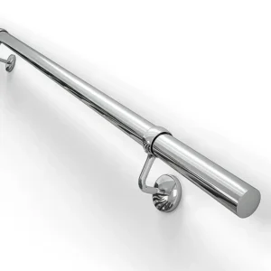
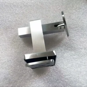
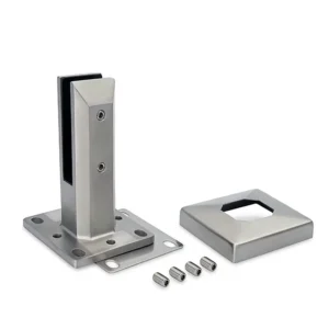
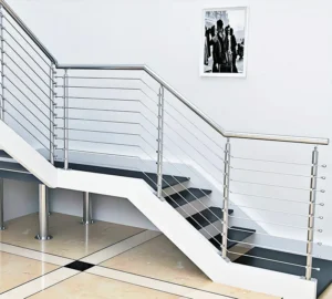
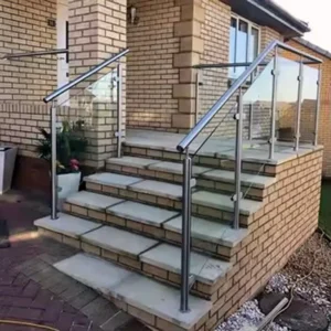
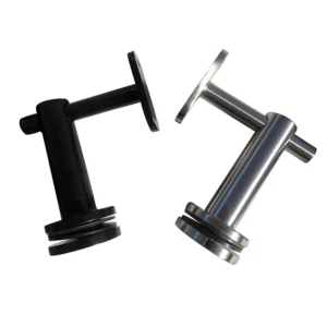
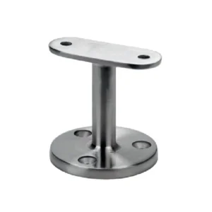
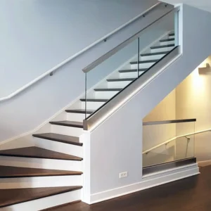
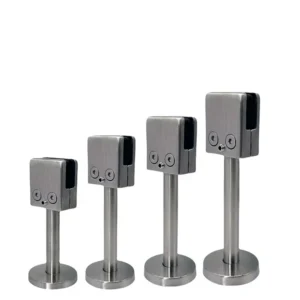
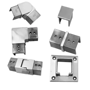
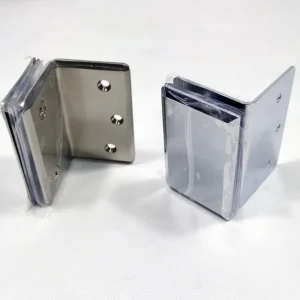
Rod infill components can support a clean railing layout, but “rod” does not define a complete product. The correct package depends on rod orientation, section, span, end form, connection, post preparation and the project’s opening and loading criteria. A buyer can begin with a sketch or photograph; the production configuration should be frozen later on an approved bay schedule and connection detail.
Request a Rod Infill Component Quote on WhatsApp
Choose the rod duty and orientation first
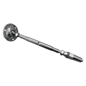
Some projects use rods as rigid members captured between posts or rails. Others show threaded ends, mechanical holders or an assembly that is adjusted during installation. Those details affect end machining, tolerances, replaceability and the way force reaches the supporting structure. Do not describe a rigid rod automatically as a tensioned cable, or assume that every visible end can be adjusted.
| Decision | What to define | Procurement consequence |
|---|---|---|
| Orientation | Horizontal, vertical, raked with a stair or another drawn direction | Changes opening measurements, cut lengths, connection direction and transition details |
| Section | Requested outside form and size; solid or hollow where already specified | Affects stiffness, weight, machining and compatible end fittings |
| Support condition | End-supported only, through-post, intermediate support or framed assembly | Changes unsupported length, deflection control and the number of interfaces |
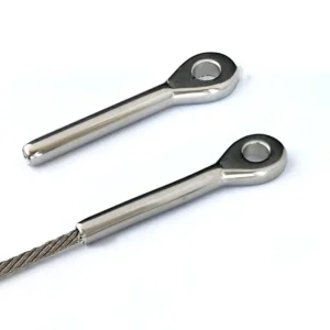
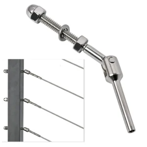
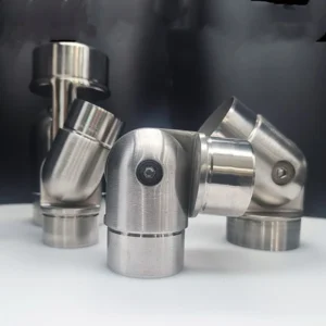
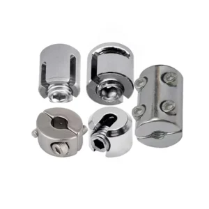
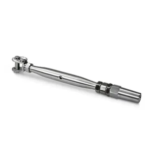
| End form | Plain cut, threaded, stepped, drilled, sleeved or matched to a specific holder | Determines whether the rod can be installed, retained and serviced as intended |
The governing project team must establish the permitted openings, guard height, loads, climbability and any deflection limit. ESANG can prepare components to an agreed configuration, but the rod alone does not certify the complete railing.

Match rods, holders and posts as one interface
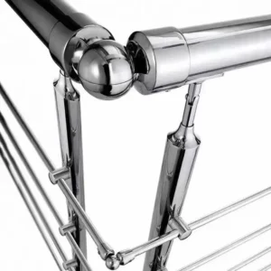
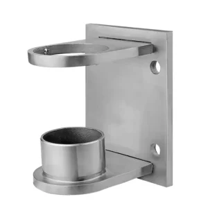
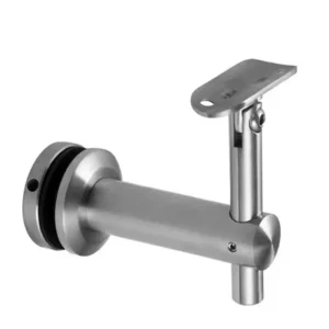
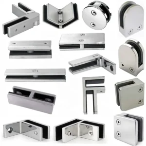
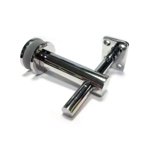
For a through-post route, the drawing should show hole diameter, hole location, post wall condition, sleeves or bushes, rod retention and the installation sequence. For face-mounted rods, identify the holder footprint, fastener access, stand-off distance and whether the holder must suit a round, square or flat mounting surface. For captured rods between rails, define receiver depth, drainage and end clearance.
Ask the quotation to separate the following items:
- rod lengths and any end machining;
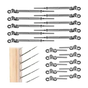
- holders, sleeves, bushes, nuts, caps or locking parts;
- post or rail drilling and any templates;
- intermediate supports or spacer elements;
- fasteners and isolating parts; and
- site work such as cutting, threading, welding, adjustment and final locking.
A mixed-source assembly can fail at an interface even when every individual part looks suitable. Rod diameter does not prove compatibility with a holder, and an external thread does not prove its pitch, engagement or material. Freeze the mating dimensions on the approved drawing.
Control openings and alignment by bay
For horizontal rods, state the clear vertical opening and row count. For vertical rods, state the clear horizontal opening and the distance from end rods to posts. If the design uses centre-to-centre pitch, also show the rod width so the clear opening can be checked. Different bay heights or widths can require a changed pitch or a special end gap; one typical detail is rarely enough for every condition.
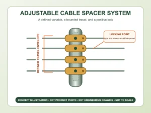
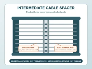
Long horizontal runs can show visible waviness if posts, holes or holders are not aligned. Identify the datum from which rows are set out and how tolerances accumulate. If an intermediate restraint is required, show its location and whether it is structural, an alignment device or only a visual spacer.
Detail corners, returns and stair transitions
Corners
State whether rods terminate at a corner post, pass through it, or connect to a separate return fitting. Provide a plan view showing which face each rod line uses. A corner can require different hole depths or fastener access from an intermediate post, and the supporting post must be assessed for the actual combined layout.
Stairs
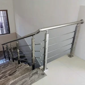
Mark whether rods stay level, remain plumb, or run parallel to the stair rake. Provide the stair angle, transition point and actual post locations. A raked rod can require angled drilling or a pivoting holder; that must be proposed and confirmed rather than assumed from a generic component image.
Ends and gates
Wall returns, gate leaves and removable sections need an end-retention plan. Identify whether the rod must be removable, tamper-resistant or permanently fixed, and maintain the project-defined opening at both sides of the terminal member.
Separate material requests from confirmed supply
Describe the exposure—interior, exterior, coastal, poolside, industrial or chemical cleaning—and state any requested alloy and finish. The ESANG proposal should confirm the actual material and finish of rods and every mating fitting. Do not infer alloy from colour or polish, and do not assume that a fitting and rod shown together use the same material.
For hollow components, specify closure or drainage. For threads and close-fitting sleeves, discuss contamination, water traps and maintenance access. Where dissimilar metals meet, the project team should review isolation and corrosion risks. Assign any site cutting, thread repair, welding, finishing or passivation before the order is placed.
Information that moves an inquiry forward
Initial review
- plan, elevation, sketch or clear photographs;
- approximate run lengths and number of bays;
- horizontal, vertical and stair conditions;
- preferred rod appearance and any known section;
- post and rail profiles; and
- whether loose rods, a cut kit or a more complete assembly is being requested.
Production release
- bay-by-bay dimensions, row or rod count and clear openings;
- rod section, solid or hollow condition and cut schedule;
- end machining, threads, holders, sleeves and locking method;
- post or rail preparation and allowable site adjustment;
- corners, stairs, transitions, walls and gate interfaces;
- material, finish, exposure and documentation needs; and
- responsibility for engineering, anchors, installation and final inspection.
Compare the complete proposed configuration
A comparable quotation should list the actual rods, end forms, holders, intermediate supports, fasteners, material, finish, supplied lengths, machining, quantity and packaging basis. It should identify which post and rail preparation is included, what field adjustment remains, and which components or services are excluded. If a supplier quotes plain rods while another quotes machined rods plus holders, the headline price is not comparing the same work.
Common questions
Are rod infill and cable infill the same?
No. Cable systems typically depend on flexible cable, terminals and controlled tension. Rod systems may use rigid or semi-rigid members and different supports. The drawings and quotation should name the actual operating principle.
Can rods be cut on site?
That depends on the end form, finish and installation method. Plain ends may be more tolerant of field cutting than threaded or stepped ends, but the responsible party must define how the cut is measured, finished and protected.
Does a larger rod automatically solve the span?
No. Section is only one input. Support condition, connection stiffness, spacing, load path, post behaviour and project limits also control the design.