Cable Spacer Bars
Cable Spacer Bars
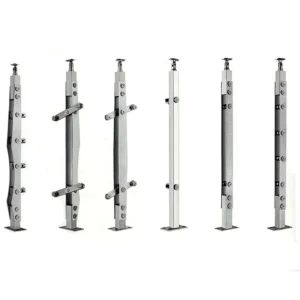
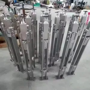
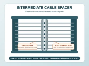
Cable spacer bars sit between structural posts to organize several cable rows and help hold their planned positions. They are an intermediate support component—not automatically a terminal post, a tensioner, or a substitute for the railing frame. Select a spacer from the row layout, cable passage and mounting detail shown on the project drawing.
Discuss Cable Spacer Bars on WhatsApp
Use the Product Routes as Inquiry Starting Points
• Intermediate Cable Spacers — start here for a spacer located between two structural posts. Provide row positions, overall length, cable passage and attachment detail.
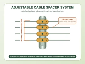
• Adjustable Cable Spacer Systems — use this route only when the drawing needs a defined field adjustment. Ask the proposal to identify what moves, the permitted range and how the position is locked.
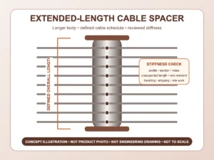
• Extended Length Spacers — use the route name to request a project-specific overall length; “extended” is not a dimension or a promise of every length.
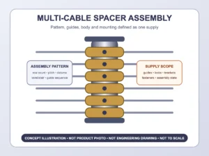
• Multi-Cable Spacer Assemblies — start here when one component organizes several cable rows. State the number of rows, their centres and the way each cable passes or fastens.
Define the Spacer’s Exact Job
Row-position support
The spacer can keep a repeated pattern of cable rows between posts. It should be detailed against the project’s intended row positions and cable path. The spacer does not by itself establish an allowable opening, post spacing or guard compliance.
Intermediate restraint
Some layouts use an intermediate component to limit visible cable movement or keep cables from spreading between posts. The complete frame, cable tension, terminal design and project requirements still govern system behaviour. Do not turn the category name into an unverified performance claim.
Stair or sloped layout
On stairs, horizontal row spacing on an elevation is not the same as the spacing measured along the sloped member. Provide the stair pitch, spacer orientation and hole or attachment coordinates so the proposed component follows the actual cable axes.
Pass-Through, Captured or Attached Cable
The drawing should show how each cable meets the spacer. A cable may pass through a finished opening, be held by a separate insert, or attach with a defined fitting. Each approach changes the hole or fitting geometry, assembly sequence, replacement access and visible finish. Ask the quotation to identify the proposed method rather than assuming the same detail for every spacer route.
If the cable passes through a hole, confirm the finished edge or insert, cable diameter, approach angle and whether the cable moves during tensioning. If the cable is captured or attached, confirm the small parts, fastener access and how the row position is locked.
Coordinate the Spacer with the Rest of the System
• Tensioners & Turnbuckles set or adjust the cable; the spacer does not replace them.
• Cable End Fittings terminate the run; the spacer is an intermediate component.
• Through-Post Hardware handles cable passages in structural posts; a slender spacer bar should not be assumed to carry the same responsibility as a post.
• Terminal and intermediate posts, top rail, bases and anchors remain part of the complete railing frame and must be coordinated separately.
Information to Send for a Spacer Inquiry
• elevation or sketch with structural-post positions and each proposed spacer location;
• number of cable rows and centre position of every row;
• cable diameter and construction;
• overall spacer length, end clearances and orientation;
• straight, stair or other sloped cable direction;
• pass-through, captured or attached cable detail;
• spacer attachment at top, bottom or another support;
• requested adjustment, if any, and how it should be locked;
• exposure, proposed material grade, finish, quantity and destination.
Quotation Fields to Compare
• overall geometry and row coordinates;
• cable passage or attachment detail and included inserts or fasteners;
• attachment to the surrounding railing and required access;
• any adjustable feature, range and locking method;
• proposed material grade and finish, with requested evidence;
• included components, exclusions, packing unit and quantity basis.
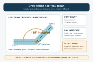
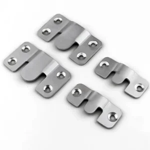
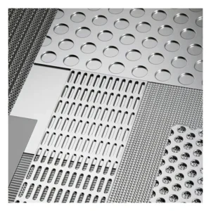
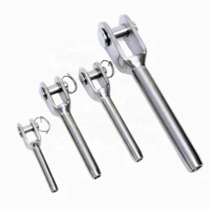
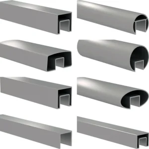
The main visual is a selection diagram, not a product photograph. Require the proposed spacer drawing or sample to identify the actual form, cable passages and fixing detail before ordering.
Related Posts:
Handrail Tube Only or a Complete Component Package: What Should the Supplier Quote Include?
Compare tube-only and component-package handrail quotes by separating fittings, fabrication, mounting interfaces, finish work and delivered quantities.
Continuous or Sectional Handrail Supply: Which Split Strategy Fits Transport and Site Assembly?
Compare continuous and sectional handrail supply using delivery access, joint locations, mating details and section identification before fabrication release.
Where Should a Handrail Change from Wall-Supported to Post-Supported Along a Mixed Route?
Choose a handrail support change by comparing wall and post interfaces, preserving the gripping path and locating the transition on coordinated drawings.
Level, Raked or Raked-to-Level Mesh Panels: Which Geometry Belongs on Each Railing Run?
Choose between level, raked, and raked-to-level mesh panel geometry by railing run, pattern orientation, interfaces, and project drawings.
How to Specify Internal Sleeves and Splice Locks for Handrail Tubes
Specify handrail sleeves and splice locks by the actual tube interior, required retention and installation access so the connector can fit and be secured.
Where Should Handrail Splices and Supports Go on Long Runs?
Locate splices with supports, transitions and assembly access so shipping breaks also work as documented connections in the installed handrail.
Esang's Projects

Esang's Certificate
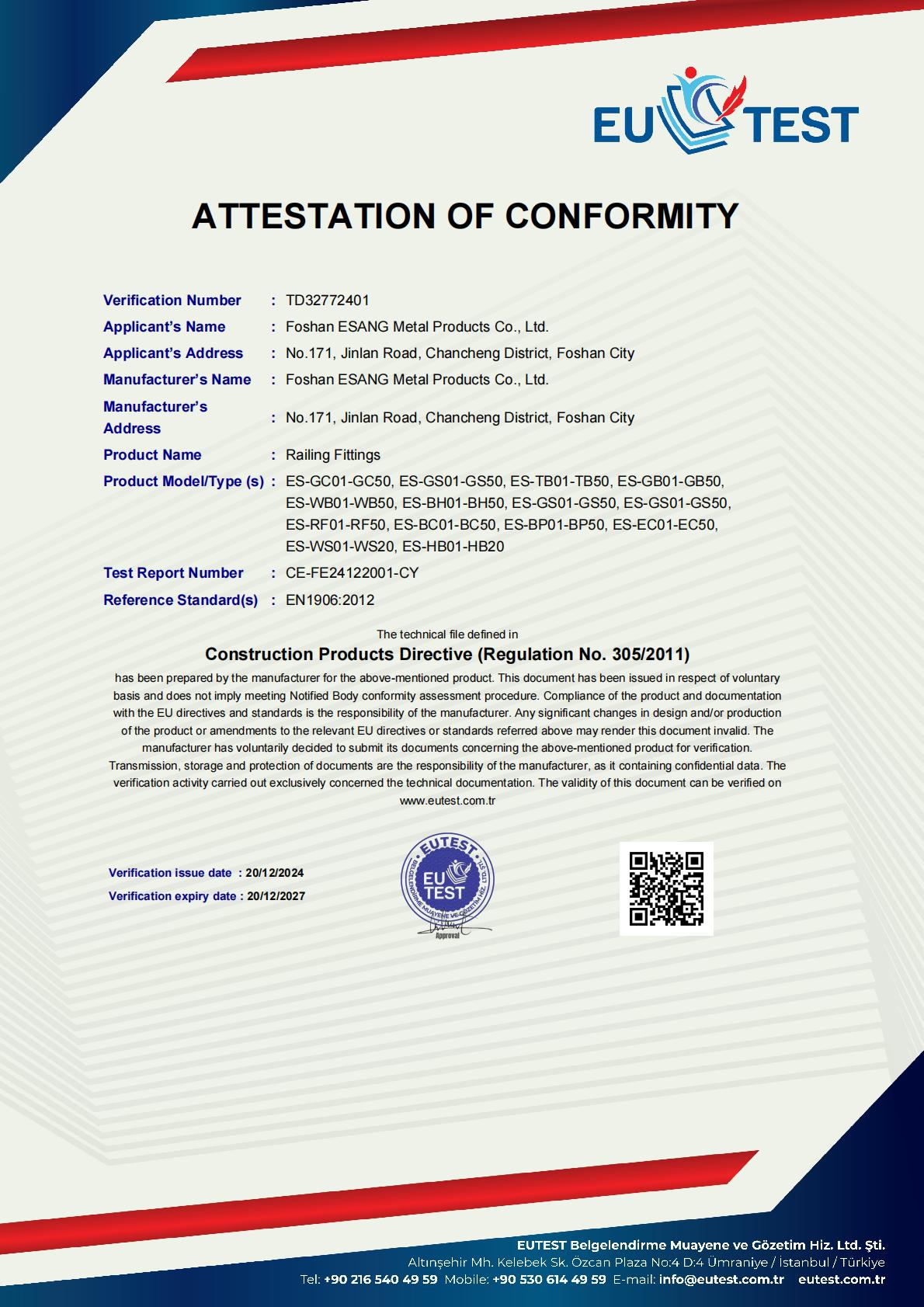
Foshan ESANG Metal Products proudly maintains CE certification (Verification No. TD32772401) under the Construction Products Directive (Regulation No. 305/2011), affirming our commitment to the highest European safety and quality standards.
Certified Product Range:
Our comprehensive railing fittings portfolio—including glass clamps, tensioners, brackets, wall mounts, base shoes, handrail fittings, cable hardware, and post components—meets EN1906:2012 standards, ensuring structural integrity and performance reliability across all installations.
What This Means for Your Project:
✓ Full regulatory compliance for European and international markets
✓ Independently verified safety and durability performance
✓ Documentation support for architectural specifications
✓ Peace of mind from third-party quality assurance
Certification valid through 2027 | Test Report: CE-FE24122001-CY
Esang's Projects


Reference Products