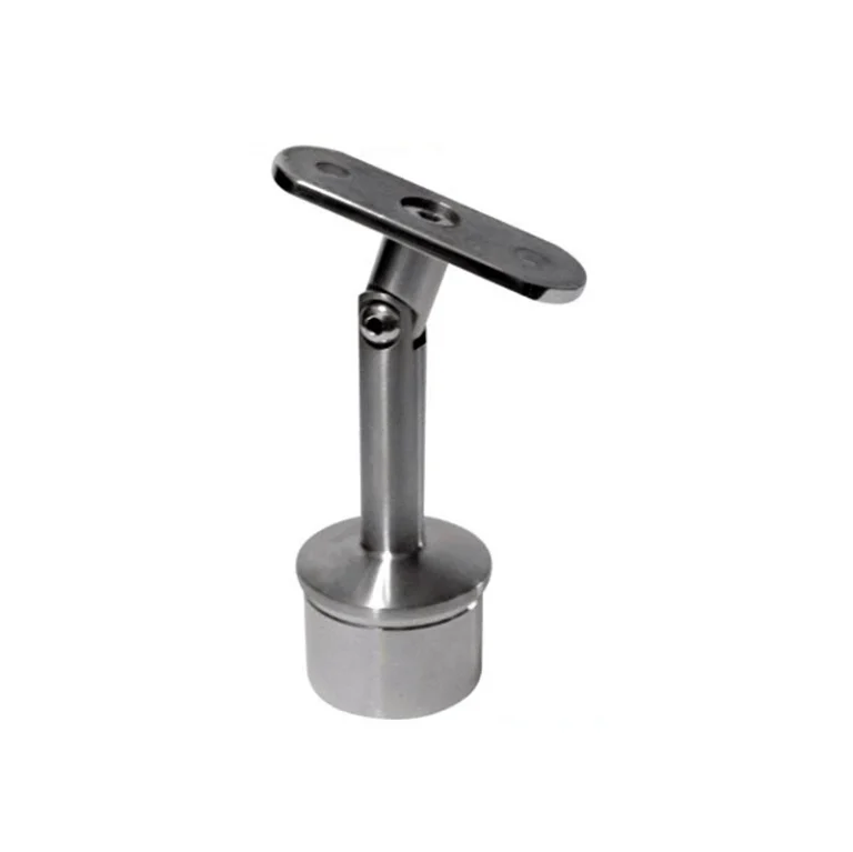
Choose the pivot plane before the angle
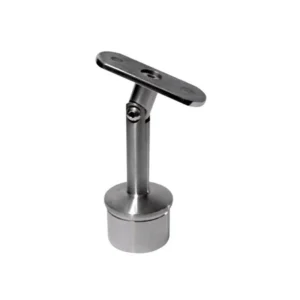
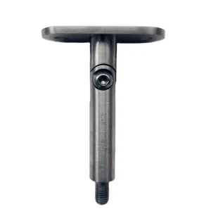
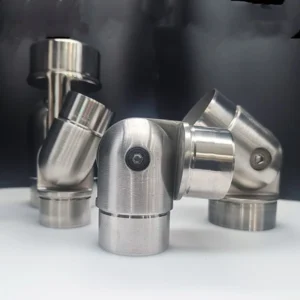
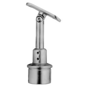
An angle adjustable bracket changes the orientation of a saddle, plate or connected member around a defined pivot. It is a fit-up component for stairs, ramps, transitions and other non-level routes—not a promise of any angle, any rail or any support. A useful enquiry identifies the design angle, how it is measured, the pivot plane, the final lock and both mating interfaces.
Start with a side-view sketch or photo, the rail route, support type, required angle and estimated quantity. ESANG can use incomplete information to identify missing fit fields; the proposed range and locked position must be shown before order.
Request an angle adjustable bracket quote on WhatsApp
Use one angle convention
State whether the angle is measured from horizontal, vertical, the support face or the centreline of the adjoining rail. A “30° bracket” can describe different orientations if the reference line is omitted. Also state whether the pivot turns in the side elevation, plan view or another plane. The same nominal angle in the wrong plane cannot follow the intended route.

Specify the whole angle-setting chain
| Decision | What the request should show | Mismatch consequence |
|---|---|---|
| Design angle | Target angle and its reference line at each bracket location | A correct numeric value measured from a different baseline produces the wrong rail line. |
| Pivot plane | Side-elevation, plan-view or other rotation; pivot-axis direction | The saddle may rotate but still cannot follow the actual route. |
| Required range | Minimum/maximum setting around the design angle, with end positions shown | The design angle may sit at an inaccessible end stop or outside the real movement envelope. |
| Final lock | Locking fastener, tightening sequence, access and anti-rotation feature | The selected angle can move while tightening or remain vulnerable to unintended rotation. |
| Carried surface | Round saddle, flat plate, receiver or requested connection; member dimensions and holes | The angle can be correct while the carried member lacks full contact or fastening access. |
| Support interface | Post, wall or plate form, dimensions, hole pattern and fixing face | The pivot head may suit the rail but the bracket body may not suit the post or wall. |
| Clearance | Neighbouring rail, cover, glass/wall, fasteners and tool path through the full arc | The mechanism can collide before reaching or locking at the required angle. |
Angle, height and alignment are different variables
Rotation changes orientation. It does not automatically add vertical travel, lateral translation or projection adjustment. In fact, rotating a saddle can change its effective height and projection, so the drawing should show the locked geometry at the project angle—not only at a neutral position.
If site survey shows position error as well as route angle, treat them as separate requirements. A separate height mechanism, slotted interface or revised support may be needed, but only the functions shown in the accepted assembly should be assumed. Angle adjustment cannot compensate for incorrect structural positioning or replace engineering review of the completed connection.
Match the bracket to both neighbours
- Rail or carried member: profile, outside dimensions, wall thickness where relevant, hole/weld request, centreline and visible finish.
- Bracket: pivot body, saddle/plate, locking fastener, washers or bushings, anti-rotation detail and covers.
- Support: post, wall or mounting plate geometry, backing, fixing pattern, edge clearance and installation access.
- Supply boundary: list rail fasteners, support anchors, adapters, covers, isolators, sealants and special tools as included or excluded.
Decide where adjustment happens
A factory-set bracket can arrive at a stated angle or with a reference mark, while an installer-set bracket requires accessible locking hardware and a field sequence. Those are different procurement requirements. The quotation should state whether adjustment is for initial installation only or is intended to remain serviceable, and what inspection or re-tightening instructions apply to the proposed configuration.
The factory scope is to return the proposed angle convention, range, pivot axis, locked geometry, mating dimensions, hardware and material/finish in the drawing or quote. The site scope includes survey, substrate and anchor review, setting the route, final tightening and verifying the completed rail. Neither side should leave the target angle or reference line implicit.
Compare proposals field by field
Use a common comparison sheet for design angle; reference line; pivot plane and axis; minimum/maximum angle; neutral and locked geometry; carried and support interfaces; lock and anti-rotation method; tool clearance; material/finish request; included/excluded hardware; quantity and packaging; drawing revision; and any project-specific performance evidence needed for acceptance.
Frequently asked procurement questions
Does angle adjustable mean 0–90° or 360°?
No range follows from the name. Ask the proposal to show the usable arc and end positions for the exact configuration.
Can one angle bracket work on every stair slope?
Only when the required slope falls inside its usable range and the rail, support, lock and clearance all match. Stair geometry and project responsibility still need confirmation.
Can the installer set the angle by eye?
The field team needs a project datum or route line and the agreed tightening sequence. A visual match alone does not establish the designed orientation or completed connection.
Is a pivoting saddle the same as a variable-angle system?
A pivot is one mechanism. A variable-angle system may also require a stated family of setpoints, repeatability, end stops or multiple axes. Buy the functions shown, not the label.
Can the pivot remain moving in service?
Do not assume so. Unless the proposal specifically defines a serviceable moving joint, treat the pivot as an installation adjustment that must be locked at the accepted angle.
Send the route angle and interfaces
Share a side-view sketch, the angle reference, target and possible range, support profile, carried-member profile, fixing access, environment and quantity. Ask the response to show the pivot plane, locked position, clearance and included hardware so competing proposals can be compared on the same geometry.