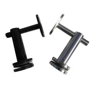
Plan continuity across the route, not just along one tube
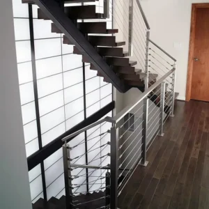
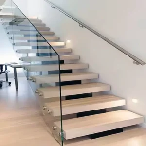
A continuous wall handrail system coordinates rail sections, wall brackets, joints, corners, slope changes, landings and end returns so the user can follow the intended route. “Continuous” does not necessarily mean one factory-length piece. Transport limits, fabrication, site access and the approved handrail detail determine where physical joints occur and how the gripping path is maintained.
Request a continuous handrail system quote on WhatsApp
Begin with the route drawing or a sequence of photos. Approximate lengths are enough for an initial component review if every landing, turn and termination is visible.
Turn the route into a rail and fitting map
Straight runs and fabrication lengths
List each run separately and note lifts, narrow doors, site storage and finishing restrictions. The quotation should propose practical piece lengths and label factory-fabricated versus field-made work. A long nominal run can still require straight joiners, and a short run may need a special return or transition.
Slope changes, corners and landings
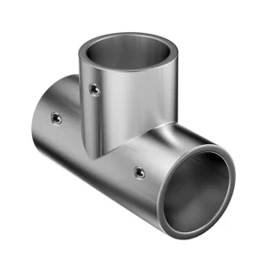
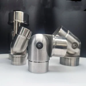
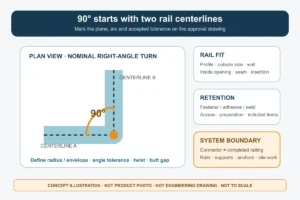
Identify the angle between every adjoining run. Fixed elbows, adjustable fittings, formed bends and fabricated corners create different visible joints and installation tasks. Ask which option is proposed at each location and whether the finished joint interrupts the gripping surface.

Ends, returns and transitions
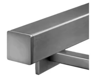
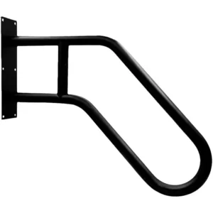
Show whether each end returns to a wall, turns down, continues into another rail, or terminates with a cap under an approved detail. Extensions and returns are governed by the applicable project requirements; they should not be selected from appearance alone. A quotation should list the end treatment for every run, not leave it as an unpriced site decision.
Coordinate support positions with joints and the wall
A continuous gripping route still relies on discrete brackets and anchors. Provide the structural wall type, finish thickness, verified backing and any prohibited drilling zones. Bracket positions must be coordinated with rail joints, corners, expansion or movement details, wall framing and project loads. A generic spacing rule is not a substitute for that coordination.
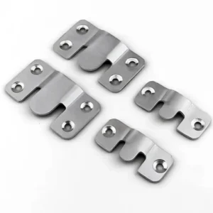
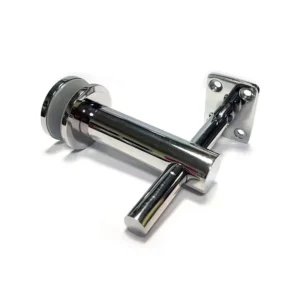
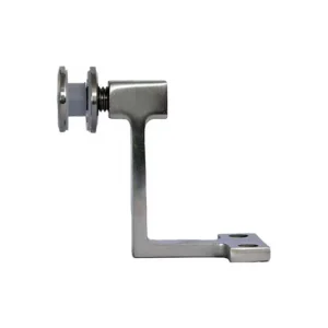
- Fixed brackets suit known geometry and keep the component count simple.
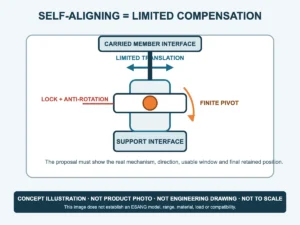
- Angle-adjustable brackets may help at sloping runs but require a defined locking position and matching rail support.
- Projection or alignment adjustment can accommodate finish build-up or construction tolerance; it does not correct missing structural backing.
- Joint support needs an intentional detail. Confirm whether a rail joint may occur at, near or away from a bracket for the proposed connector.
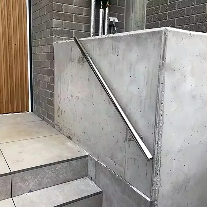
Decide how joints and finish will be completed
Mechanical sleeves, set-screw connectors, adhesive-assisted joiners and welded joints do not share the same site process or visual result. Ask the supplier to identify the proposed connection, required access, consumables, curing or finishing work, and whether disassembly is expected. If the design calls for a visually uninterrupted surface, agree how joint lines, fasteners and finish direction will be handled before production.
For stainless rail, also state indoor or outdoor exposure, salt or chemical contact and the desired finish. The proposed material and finish should be identified separately for rail sections, connectors, brackets and visible fasteners. Do not infer system durability from the rail tube alone.
What a useful system quotation should return
- a run-by-run rail schedule with profile, proposed material, finish and piece lengths;
- a fitting schedule for straight joints, slope changes, corners, transitions, returns and caps;
- bracket type, proposed quantity and the basis used for locations or spacing;
- wall attachment assumptions and a clear statement of included or excluded anchors;
- factory work versus site cutting, drilling, joining, welding or finish repair;
- drawings, installation information and any project-specific evidence available for the exact configuration.
If the principal decision is round versus square gripping geometry, resolve that on the corresponding profile page. If the principal decision is a documented non-standard duty rating, treat it as a separate heavy-duty wall handrail requirement. This page focuses on route continuity and component coordination.
Send the whole route, even when final dimensions are pending
Share a plan or marked-up photos, each run length, floor-to-floor or stair geometry, corner and landing conditions, end details, rail profile, wall construction, environment, quantity and destination. Identify the applicable jurisdiction and attach an approved accessibility or architectural detail when one controls the route.