Which dimensions on a railing hardware drawing actually determine whether an inspection catches a real fit or load problem, and which ones just add paperwork? That question matters because the same fabricated post, bracket, or clamp can pass a careless check and still fail on site when it meets glass, cable, or an adjoining tube. The answer depends on classifying dimensions by the function they control, not by habit or by what a template happens to list.
Dimensions That Control Fit, Load Transfer, Alignment, or Installation Access
| Control function | Critical-dimension question |
|---|---|
| Mating fit | Does the dimension control whether the named hardware interfaces fit? |
| Load transfer | Does the dimension control load transfer through the named hardware? |
| Alignment | Does the dimension control the required alignment? |
| Adjustment range | Does the dimension set the available adjustment range? |
| Accès à l'installation | Does the dimension control access needed for installation? |
A dimension earns inspection attention when it controls something the assembly depends on: whether two parts mate, whether load passes cleanly from one component to the next, whether the installed hardware sits at the required alignment, whether an adjustable connection has the range a site condition demands, or whether an installer has the physical access needed to complete the connection. Dimensions that do not affect any of these can still appear on a drawing, but treating every dimension as equally critical dilutes the inspection effort and makes it harder to catch the ones that matter.
Mating fit depends on how two surfaces or features engage, so the controlling dimension is whichever one sets that engagement, whether it is a bore diameter, a tube outside diameter, or a flange seating depth. Where a component is designed to telescope, clamp, or seat against another, the critical dimension is the one that sets the contact or clearance at that interface, not an unrelated overall length that does not affect how the parts meet.
Load transfer works differently. A dimension controls load transfer where its value changes how force moves from the hardware into the structure or from one fitting into the next. Wall thickness on a tube, engagement depth on a threaded connection, or contact area on a glass-bearing surface can each function this way depending on the hardware family. Where a dimension affects only appearance or ease of handling and does not change how force passes through the joint, it does not belong in the load-transfer category even if it appears on the same drawing sheet.
Alignment dimensions set the position or angle a component must hold relative to another part of the system, such as the plane a bracket must maintain or the position a post must occupy relative to its neighbors. Adjustment range is a related but separate category: it describes how much variation an adjustable fitting can absorb, which matters where the field condition cannot be controlled precisely during fabrication. Installation access concerns whether the geometry at a connection leaves room for the tool, fastener, or hand motion the installation method requires; a dimension that is otherwise correct can still create an installation problem if it closes off the access the method depends on.
The same physical dimension can fall into more than one category depending on the hardware and the assembly, so the reader classifying it should ask which function or functions that dimension actually governs in the specific design, rather than assuming a fixed label.
Family-Specific Checks for Tubes, Holes, Threads, Brackets, Glass, and Cable Interfaces
| Hardware family or interface | Critical dimensional check |
|---|---|
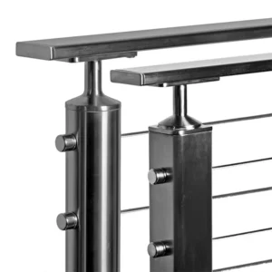
| Tube | Diameter and wall |
| Hole | Localisation |
| Thread | Engagement |
| Support | Angle |
| Glass-contact hardware | Glass-contact geometry |
| Cable terminal | Cable-terminal interface |
Railing hardware is not one part family with one inspection checklist; it is several part families, each with a dimensional behavior that the others do not share. Treating a tube check and a bracket check as interchangeable because both appear under “railing hardware” produces inspection gaps, because the geometry that threatens a tube joint is not the geometry that threatens a glass-contact surface or a cable terminal.
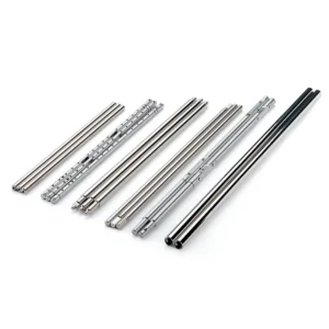
Tube diameter and wall thickness govern how a tube seats inside a fitting, how much material resists deformation under clamping or load, and how consistent the tube is along its length. ISO 1127 addresses stainless steel tube dimensions, tolerances, and conventional masses, which gives the dimensional basis for tube diameter and wall checks; it does not establish railing load capacity, finish, weld quality, or code compliance, so a tube that satisfies this dimensional scope still requires separate confirmation of those other properties for the specific assembly.
Hole location determines whether a fastener, pin, or connector lines up with its mating feature without forcing the assembly out of alignment to compensate. A hole that is correctly sized but mislocated can still produce a joint that only appears acceptable until load or vibration reveals the misalignment.
Thread engagement concerns how much thread length is actually carrying the joint, not merely whether a fastener starts. Where fastener material is stainless steel, ISO 3506-1 addresses mechanical and physical properties and property classes for corrosion-resistant stainless fasteners; it supports verifying grade, class, dimensions, temperature, and joint environment, but it excludes torque, shear, fatigue, and weldability design, so engagement adequacy for a specific joint remains a separate confirmation from fastener grade.
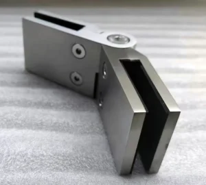
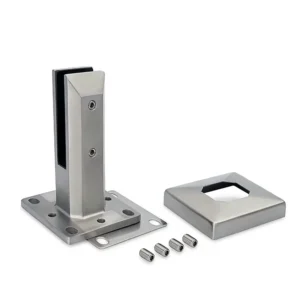
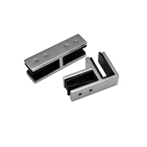
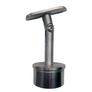
Bracket angle controls whether a handrail or connecting member sits at the orientation the assembly requires; an angle error compounds wherever the bracket connects to a run of multiple fittings. Glass-contact geometry in glass-clamp or spigot hardware governs how the hardware bears on the glass edge or face, which is a different concern from the glass thickness the hardware is rated to accept. Cable-terminal interfaces govern how a cable end engages its fitting, which depends on the terminal geometry rather than on the cable’s general diameter alone. Each of these checks requires its own method because the failure mode it guards against is specific to that family.
Datum and Tolerance Definitions on the Controlled Drawing
A dimension without a stated datum and tolerance is not yet an inspectable requirement; it is only a nominal value. The datum establishes the reference feature or surface from which the dimension is measured, and the tolerance establishes the acceptable range around the nominal value. Where the controlled drawing does not state both, two inspectors can measure the same physical part from different reference points and reach different conclusions about whether it passes.
The datum choice matters because it determines what the measurement is actually verifying. A hole location measured from one edge of a bracket tells the inspector something different than the same hole measured from the bracket’s mounting face, even though the hole itself has not changed. Where the assembly’s critical relationship is between the hole and the mounting face, the datum should reflect that relationship; a datum chosen for drawing convenience rather than for the governing interface can let a part pass inspection while still failing to mate correctly in the field.
Tolerance width carries its own trade-off. A tight tolerance increases the likelihood that an individually inspected part will fit as intended, but it also narrows the range of acceptable fabrication outcomes and may constrain what a supplier can produce without additional process control. A wider tolerance gives fabrication more flexibility but places more weight on downstream checks, including assembly trials, to catch cases where several dimensions near the edge of their individual tolerances combine into an unacceptable result. Where the inspection plan treats tolerance purely as a pass or fail line without recording how close to the edge a measurement falls, it loses information that would help explain why an assembly trial later fails even though every individual dimension passed.
The controlled drawing, not a general reference drawing or a supplier catalog sheet, is the document that should carry this datum and tolerance information for the specific order, because project-specific requirements such as those illustrated in structures like UFGS 05 52 00 Garde-corps métalliques are defined per project rather than universally; that document’s structure is an example of how a specification, drawing, and submittal package can be organized, not a code the reader’s project is assumed to follow.
Measurement Methods Matched to Each Critical Dimension
A tolerance only controls outcomes if the measurement method used to check it is capable of resolving that tolerance and consistent with how the dimension was defined. A method that cannot distinguish within the stated tolerance range will pass parts that should fail, or reject parts that are actually within range, regardless of how carefully the datum and tolerance were specified.
The method needs to match the geometry it is measuring. A diameter check on a tube calls for a method that captures roundness and consistency along the tube’s length, not a single-point measurement that could miss variation elsewhere on the same part. A hole-location check depends on referencing the same datum the drawing specifies; measuring from a different feature, even an adjacent one, can produce a result that does not reflect what the drawing actually requires. Thread engagement is not verified the same way a smooth-bore diameter is, because the relevant question is how much thread length is actually functional, which calls for a method suited to that specific geometry rather than a general length measurement. Bracket angle, glass-contact geometry, and cable-terminal interfaces each raise the same issue: the measurement approach has to correspond to the feature’s actual geometry and to the datum already defined for it, rather than defaulting to whatever instrument is on hand.
Where a project specifies a dimension but leaves the measurement method unstated, the inspection plan should establish that method rather than let it vary by inspector or by site. Two measurements of the same nominal dimension using different methods can produce different numeric results even when both methods are reasonable in isolation, because each method carries its own reference assumptions and its own capability to resolve small variation. This is a project-specific decision that depends on the equipment available, the feature being measured, and the tolerance it must resolve; the buyer and supplier need to confirm which method applies to which dimension before inspection begins, rather than assuming that any method capable of producing a number is equivalent to any other.
Assembly Trials for Detecting Cumulative Tolerance Problems
| Individual dimension result | Assembly-trial result | Interpretation |
|---|---|---|
| Meets the applicable acceptance rules | Meets the project-specific assembly acceptance rule | No cumulative tolerance problem is detected by the trial |
| Meets the applicable acceptance rules | Does not meet the project-specific assembly acceptance rule | The trial detects an unacceptable cumulative tolerance problem despite acceptable individual dimensions |
Individual dimensional checks confirm that each part, considered on its own, falls within its stated tolerance. They do not confirm that the parts function correctly once combined, because tolerances on separate dimensions can each sit near the edge of their acceptable range in a direction that, individually, causes no failure but that compounds once the parts are assembled together. This is the distinction an assembly trial is positioned to catch and that single-part inspection cannot.
Where a tube’s diameter sits at one edge of its tolerance and the fitting it mates with sits at the corresponding edge of its own tolerance, the two parts can still assemble, but the resulting fit may be tighter or looser than either part’s individual inspection suggested. Where several such near-edge dimensions occur across a run of handrail brackets, a hole pattern, and the connecting hardware between them, the cumulative effect can produce misalignment, interference, or a load path that behaves differently from the single-part engineering assumption, even though every part involved passed its own inspection.
An assembly trial addresses this by physically combining the parts, or a representative subset of them, and checking the assembled result against a separate acceptance rule defined for the assembly rather than for any single component. Where the trial result meets that assembly-specific rule, the combination of individually acceptable dimensions has not produced a cumulative problem for this build. Where the trial result does not meet that rule, the trial has revealed a tolerance stack that no single dimensional check would have caught, because each contributing dimension was independently acceptable.
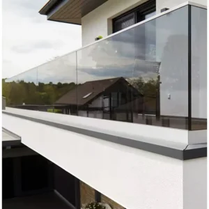
This distinction matters most where an assembly includes several independently toleranced interfaces in series, such as a railing run with multiple post-to-bracket connections or a glass system with multiple clamp-to-glass contacts, because the number of independent dimensions in series increases the opportunity for individually small variations to combine. Where the assembly instead depends on a single dominant interface, the risk of an undetected stack is lower, though it is not eliminated simply because fewer interfaces are involved. The project team deciding whether to require an assembly trial, and at what stage of fabrication or site installation to run it, needs to identify which interfaces in the specific assembly carry this compounding risk before deciding the trial is unnecessary.
Acceptance Rules Tied to the Drawing, Inspection Plan, and Order
| Acceptance source | Detail to check |
|---|---|
| Controlled drawing | Critical dimension, datum, and tolerance |
| Inspection plan | Measurement method and acceptance rule |
| Order | Applicable project-specific acceptance rule |
A critical dimension, a defined datum and tolerance, and an appropriate measurement method together establish what can be measured and how, but they do not by themselves establish what happens when the measurement is taken. That final step belongs to the acceptance rule, and the acceptance rule only functions correctly when it is consistent across every document that references it.
The controlled drawing is the source for the dimension itself, along with its datum and tolerance. The inspection plan is the source for the measurement method and for the acceptance rule that applies once the measurement is made. The order is the source for whichever project-specific requirements apply to this particular purchase, which may include options, finishes, or configurations that are not fixed across every order the supplier processes. Where these three documents disagree, for example where the drawing states one tolerance and the inspection plan references an older or more general version, the inspection result becomes ambiguous even if the measurement itself was taken correctly.
This is also the point in the process where the information the buyer supplies about the project enters the supplier’s quotation and configuration review. A customer specifying hardware for a particular tube size, glass thickness, or cable-terminal arrangement provides inputs that the supplier’s internal review checks against what can actually be fabricated and supplied for that order, and inconsistencies between what the order describes and what the drawing or inspection plan assumes should surface during that review rather than after fabrication.
Where the three documents are aligned, the acceptance rule applies cleanly: a dimension within tolerance, measured by the stated method, is accepted; one outside tolerance is not. Where a project involves hardware families covered by existing reference material, such as the distinctions between tube tolerance and finish quality that a buyer must confirm when sourcing stainless railing components, or the anchor, weld, base-plate, and site-tolerance evidence relevant at the post-inspection stage, those distinctions depend on the same underlying principle: the acceptance rule is only as reliable as the alignment between what the drawing specifies, what the inspection plan measures, and what the order actually calls for. A buyer who finds a discrepancy among these three documents needs resolution before relying on an inspection result, because the result reflects whichever document the inspector happened to follow, not necessarily the one the project intended to govern.
Questions fréquemment posées
Q : Should every railing hardware family use the same list of critical dimensions?
A : No. Select dimensions according to the function and interface of the named hardware: tube diameter and wall, hole location, thread engagement, bracket angle, glass-contact geometry, and cable-terminal interfaces call for family-specific checks. Confirm which dimensions control fit, load transfer, alignment, adjustment range, or installation access for the project.
Q : What information should a buyer prepare before agreeing on a dimensional inspection plan?
A : Prepare the controlled drawing with the critical dimensions, datums, and tolerances, then align it with the measurement methods and acceptance rules in the inspection plan and order. This gives the parties a common basis for deciding what is measured and what result is acceptable.
Q : Can individually acceptable dimensions still produce an unacceptable railing hardware assembly?
A : Yes. Several dimensions can each meet their acceptance rules while their combined tolerance stack prevents the assembly from meeting its project-specific acceptance rule. Use an assembly trial when mating parts or interfaces could create this cumulative problem.
Q : Do the cited stainless tube and fastener standards establish complete railing acceptance criteria?
A : No. ISO 1127 provides dimensional scope for stainless steel tubes, while ISO 3506-1 addresses mechanical and physical properties and property classes for covered stainless fasteners. The project still needs its own applicable requirements for the hardware interfaces, assembly, and acceptance; these references do not by themselves establish railing load, finish, weld quality, or code compliance.
Q : How can a buyer prevent the drawing, inspection plan, and order from applying different acceptance rules?
A : Check the three documents together before inspection: the drawing should identify each critical dimension, datum, and tolerance; the inspection plan should state the measurement method and acceptance rule; and the order should identify the applicable project-specific acceptance rule. Resolve any mismatch before using the result to accept the hardware.