Настенный поручень runs carry a disproportionate share of coordination risk in any shop drawing package, because the rail depends on a wall assembly the railing fabricator does not control and often does not fully see until field verification. Before a drawing is released for fabrication, the team needs to agree on what information actually locates the run, what the connection details confirm, and where responsibility for the substrate and anchor stops being the fabricator’s problem and becomes the general contractor’s or wall subcontractor’s. These are drawing decisions as much as structural ones, and getting them wrong shows up later as a bracket that cannot reach solid backing or a return that collides with a door swing.
Drawing information needed to locate every wall-mounted run
| Drawing element | Information to show | Coordination decision supported |
|---|---|---|
| Run extent | Run dimensions and elevations | Locates the run in plan and elevation |
| Sloped path | Slopes and landings | Connects the run geometry across changes in level |
| Direction changes | Corners | Shows where the run changes direction |
| Interrupted areas | Открытые вакансии | Makes interruptions visible against the run geometry |
| Run ends | Terminations | Fixes where each run stops |
| Fabrication breaks | Joint positions | Coordinates joint locations with the complete run |
A wall handrail run cannot be fabricated from a single dimension or a single elevation; it has to be located as a continuous path that a crew can walk through on paper before they walk it on site. That means the drawing needs to carry the run’s extent, its elevation relative to the finished floor or nosing line, and any slope or landing condition that changes the rail’s geometry partway through its length. Where the run changes direction, the corner has to be shown as part of that same continuous reference, not as an isolated detail disconnected from the straight runs on either side.
The reason this matters is that each of these elements interacts with the others. A slope that changes at a landing affects where a corner can occur and how a termination at the top or bottom of that slope is detailed. An opening along the run, whether for a door, a gap in the wall, or an equipment access point, interrupts the rail geometry and has to be visible against the run dimensions, not noted separately where it can be missed during fabrication layout. Joint positions depend on all of this too: a fabricator sets joints based on transportable lengths and connection locations, but those joint positions only make sense once the full run geometry, including its slopes, corners, and openings, is already fixed on the same reference.
Where a project has a single straight run with no direction changes, this coordination is simple enough that most of it can live on one elevation view. Where the run turns a corner, crosses a landing, or steps around an opening, the drawing has to carry enough plan and elevation information together that nobody has to infer how one segment connects to the next. A reader reviewing a drawing for release should be able to trace the entire run, start to finish, without switching between disconnected details that were never drawn to agree with each other.
Connection details for rail joints, corners, and terminations
A connection detail is only useful if it shows the assembled interface, not just the component that sits at that location. For a joint, a corner, or a termination, the drawing needs the rail profile actually being used, the bracket type at or near that location, how far the rail projects from the wall, the wall buildup behind it, what backing or substrate the connection depends on, who is responsible for the fastener or anchor, and whether the installer will have physical access to make that connection once adjacent finishes are in place.
The reason a component callout cannot substitute for this is that a joint, corner, or termination is where multiple decisions converge at once. A joint position chosen for fabrication-length reasons still has to land where the wall construction can support it. A corner detail depends on the rail profile’s ability to form that direction change without a separate fitting, or with one, and that choice changes the projection and wall buildup at that exact point. A termination has its own interface concerns, often involving a return to the wall or a transition to an adjacent element, and the drawing has to show that interface assembled, with the rail, the connection, and the wall condition all represented together.
Where installation access is tight, for instance where a connection falls close to a corner, an opening, or another fixed element, the drawing needs to confirm that an installer can actually reach the fastener or anchor point with the tools the connection requires. A detail that is dimensionally correct but assumes access that will not exist once walls, doors, and finishes are complete does not resolve the connection; it only defers the problem to the field. This is consistent with how a specification like UFGS 05 52 00 structures metal railing submittals and drawing requirements for a project, as an example of organizing connection information around the assembled condition rather than isolated parts, though any such structure has to be confirmed against the specific project’s own contract documents rather than assumed to apply universally.
Bracket positions, projection, and wall-build-up coordination
| Coordination check | Drawing evidence | Decision supported |
|---|---|---|
| Bracket location | Bracket positions along the run | Confirms where the rail is supported before release |
| Rail-to-bracket interface | Rail profile and bracket type | Shows the selected components as one connection |
| Rail-to-wall geometry | Projection and wall buildup | Checks the assembled relationship between the rail and finished wall |
| Доступ к установке | Access available at the connection | Shows whether the connection can be installed as drawn |
A bracket position is not just a point along the run; it is the place where three separate kinds of information have to agree before the connection can be built. The drawing has to show where the bracket falls along the run, which rail profile and bracket type are paired at that location, what projection and wall buildup apply at that exact point, and whether the connection is actually accessible for installation once the wall is finished.
These checks are separate because each one can change independently of the others. A bracket location chosen to meet a spacing or support requirement along the run may fall at a point where the wall buildup is different from the rest of the run, for example where a different wall assembly, a furring condition, or a transition between finishes occurs. The rail-to-bracket interface, meaning which profile and bracket type are being combined, determines whether the bracket can actually hold that rail at the required projection, and a change in rail profile without a corresponding review of the bracket type can quietly invalidate a projection that was correct for a different profile. The rail-to-wall geometry itself, the projection and the wall buildup, is a separate check again: the same bracket and the same rail can still fail to coordinate with the wall if the finished wall surface sits closer to or farther from the structural substrate than the bracket’s standoff assumes.
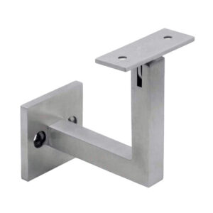
Installation access is the final check, and it depends on the other three. A bracket position and projection that work on paper can still be unbuildable if the installer cannot physically position a tool or fastener at that point, particularly where the bracket sits close to a corner, a door frame, or another wall-mounted fixture. Reviewing регулируемые настенные поручни against a specific wall buildup, rather than assuming one standard projection applies across an entire run, is part of how this coordination gets confirmed before release. Where the wall construction is consistent along the full run, this coordination can often be resolved once and applied throughout; where the wall buildup varies, for instance at a column, a recess, or a change in wall type, each bracket position in that zone needs its own check rather than relying on the typical condition shown elsewhere on the drawing.
Substrate and anchor responsibility at each mounting condition
The substrate behind a wall-mounted handrail is rarely something the railing fabricator installs, which makes the drawing’s treatment of backing and anchor responsibility a coordination document as much as a technical one. The drawing needs to identify what backing or substrate each mounting condition depends on and who is responsible for the fastener or anchor at that location, and it needs to do this at the mounting condition level rather than as a single blanket note for the whole run.
The reason a blanket note is insufficient is that wall construction is not always uniform behind a single continuous run. One segment of wall may have continuous backing suitable for a given anchor type, while another segment, perhaps where the wall changes assembly or where a penetration or opening interrupts it, may not. Where the backing differs, the anchor approach differs with it, and that in turn can change who is responsible for confirming or installing that backing before the railing fabricator’s bracket is set. A drawing that shows a single generic anchor note across an entire run risks hiding a condition where the actual wall assembly cannot support that anchor without additional backing being added by another trade first.
This is also where contractual responsibility has to be visible on the drawing itself, not left to be resolved verbally in the field. If the fastener or anchor is being specified by the railing fabricator, the drawing should say so; if the anchor or the backing it depends on is being confirmed or installed by another party, that should be equally clear. ASTM E985-24 establishes scope and basic design and load/deflection criteria for permanent metal railing systems as a public summary, but it does not resolve how a specific wall’s backing is confirmed on a specific project; that determination stays with the project’s designer and the code authority with jurisdiction, informed by the field conditions the drawing is meant to document.
Return and transition checks at stairs, ramps, and landings
| Interface to check | Drawing evidence | What the check establishes |
|---|---|---|
| Очистка | Return or transition shown against the applicable clearance | Whether the assembled interface fits the available clearance |
| Adjacent doors | Return or transition shown in relation to nearby doors | Whether the handrail interface conflicts with a door |
| Adjacent finishes | Return or transition shown against the wall buildup and nearby finishes | Whether the finished interface is coordinated |
| Hand continuity | Continuous hand path shown through the return or transition | Whether continuity is maintained across the change |
| Complete assembly | Rail, connection, and adjacent condition shown together | Prevents a component callout from standing in for the assembled interface |
A return or a transition is where a wall-mounted handrail stops being a straight run and becomes an assembled interface with something else: a clearance requirement, a nearby door, an adjacent finish, or the continuity of the hand’s path along the rail. Each of these has to be checked separately, because a return that satisfies one of them does not automatically satisfy the others.
Clearance is the most direct check: the drawing has to show the return or transition against whatever clearance applies at that location, since a return that projects correctly along a straight run can still intrude into a required clearance once it turns toward the wall or steps down at a landing. Adjacent doors introduce a different kind of conflict, where a return positioned without reference to a nearby door’s swing or hardware can create interference that was never visible when the rail and the door were drawn on separate details. Adjacent finishes raise a coordination issue rather than a clearance issue: a return has to be checked against the wall buildup and the finishes actually planned at that point, since a return detailed against an assumed wall thickness can sit at the wrong projection once the real finish is installed.
Hand continuity is a separate check again, concerned with whether a hand moving along the rail experiences an unbroken path through the return or transition, which depends on how the rail profile, the connection, and the adjacent condition are assembled together rather than on any single component. This is the clearest case where a component callout cannot stand in for the assembled interface: a bracket or fitting drawn correctly in isolation does not confirm that the rail, the connection, and the adjacent condition work together as one interface at that stair, ramp, or landing. The Access Board’s guidance on stairways addresses continuity, gripping-surface, clearance, and extension provisions for covered stair handrails within its stated accessibility scope, and where a project falls under that scope, the return or transition has to be checked against the currently adopted code rather than assumed from the general provisions alone. Reviewing straight rail joiners or similar connection hardware in isolation from the stair, ramp, or landing geometry they serve leaves exactly this assembled check undone.
Approval notes that keep field dimensions and design responsibility visible
| Approval item | What the drawing or approval note should identify | Boundary that remains visible |
|---|---|---|
| Project design criteria | The project criteria used for the drawing review | Final requirements remain tied to the project criteria |
| Field dimensions | Any dimensions that remain unresolved | Those dimensions still require field confirmation |
| Engineering and code acceptance | The contract basis for any transfer of responsibility | Supplier drawing approval does not transfer engineering or code acceptance unless the contract explicitly says so |
Drawing approval is not a single yes-or-no decision; it is a record of what the drawing was checked against and what remains outside that check. An approval note has to identify the project design criteria used for the review, because a drawing approved against one set of criteria does not carry the same meaning if the project’s actual requirements differ from what the reviewer assumed.
Field dimensions are the second item the approval record has to carry. Where a dimension remains unresolved, meaning it depends on a field condition that has not yet been verified, the approval note should say so explicitly rather than let an approved drawing imply that every dimension is final. This distinction matters because a drawing can be correctly approved for everything it was able to show while still depending on a field verification that has not happened yet; treating that approval as complete without flagging the open dimension shifts risk onto whichever party discovers the discrepancy during installation.
The third item is the most consequential: what the approval does and does not transfer in terms of engineering and code acceptance. A supplier’s drawing, however detailed, reflects the information available to the supplier at the time of drawing; it does not by itself establish that the complete installed assembly meets a project’s structural or code requirements unless the contract between the parties explicitly assigns that responsibility. This is the point where the information a customer supplies about run geometry, wall conditions, and project requirements becomes the basis for how a supplier like ESANG configures or reviews a quotation, but that configuration process is distinct from engineering sign-off, and an approval note should keep that distinction visible rather than letting drawing approval be read as design acceptance it was never intended to carry.
Where a project’s contract documents explicitly assign engineering or code acceptance to the drawing approval process, the approval note should reference that contract basis directly. Where the contract is silent or assigns that responsibility elsewhere, the approval note should make clear that responsibility remains with the designer of record and the governing code authority, not with the drawing approval itself.
Часто задаваемые вопросы
Вопрос: What should be confirmed before wall handrail shop drawings are released for fabrication?
A: Confirm each run’s dimensions, elevations, slopes, landings, corners, openings, terminations, and joint positions on one coordinated reference. Identify any unresolved field dimensions so drawing approval is not mistaken for confirmation of site conditions.
Вопрос: Can one wall bracket detail be reused for every mounting condition?
A: Only when the rail profile, bracket type, projection, wall buildup, backing or substrate, anchor responsibility, and installation access are the same. Show a separate condition wherever one of those inputs changes so the assembled connection can be reviewed accurately.
Вопрос: Who should be responsible for wall handrail fasteners and anchors?
A: Assign that responsibility explicitly for each mounting condition instead of leaving it implied. The drawing should also record the substrate or backing, wall buildup, bracket interface, and installation access needed for the responsible party to confirm the connection.
Вопрос: Is a component callout enough to coordinate a return or transition?
A: No. Show the rail, connection, and adjacent condition together, then check the assembled interface against available clearance, nearby doors, wall finishes, and continuity of the hand path.
Вопрос: Does approval of a supplier shop drawing transfer engineering or code responsibility?
A: Only when the contract explicitly establishes that transfer. Approval notes should identify the project design criteria, unresolved field dimensions, and responsibility basis, while project coverage and current adopted requirements remain subject to confirmation by the appropriate designer and code authority.