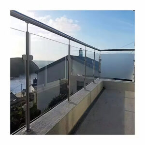
For architects and developers specifying rooftop deck railings, the primary challenge is not achieving an unobstructed view, but ensuring that minimalist aesthetic can withstand the extreme lateral loads of high-wind zones. The common misconception is that any frameless glass system offers sufficient performance, leading to costly retrofits or failures when generic solutions meet site-specific wind pressures. The real decision hinges on aligning an elegant design with engineered resilience.
This alignment is critical now, as commercial projects increasingly utilize rooftop spaces for premium amenities. Building codes are stringent, and liability for failure is high. Selecting a U-channel stainless steel system requires moving beyond catalog specifications to a performance-based approach, where material selection, glass specification, and installation integrity are non-negotiable for long-term safety and value.
Key Design & Engineering Considerations for High-Wind Zones
The Core Engineering Challenge
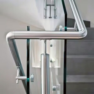
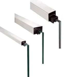
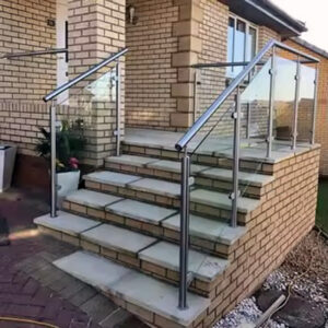
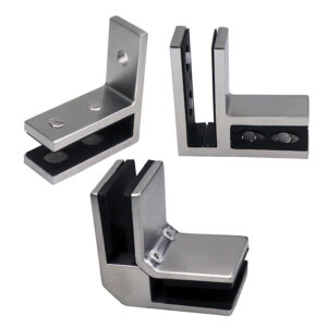
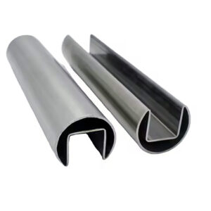
The fundamental task is resisting significant lateral wind loads while maintaining structural transparency. A U-channel system addresses this by acting as a continuous structural beam. The base shoe clamps glass panels from below, preventing slippage, while a continuous top cap adds critical stiffness. This integrated clamping mechanism is the direct answer to the primary failure mode in gusty conditions: panel displacement and wobble.
From Calculation to Integration
Performance is not assumed; it is calculated. Wind load analysis per ASCE/SEI 7 Minimum Design Loads and Associated Criteria for Buildings and Other Structures determines everything—glass thickness, panel dimensions, and anchor spacing. These loads transfer through the channel’s depth and wall thickness into the building structure. A key, often overlooked detail is accounting for parapet effects and the building’s exposure category during schematic design. Early collaboration between architect, structural engineer, and railing supplier is essential to integrate these load paths seamlessly.
The Strategic Implication for Design
This engineering rigor enables confidence. Architects can specify for exposed decks knowing the system is designed for “Extra High” wind zones. However, that confidence is contingent upon site-specific calculations. In our review of project specifications, we find the most successful projects treat the railing not as a late-stage accessory, but as an integral structural component defined during initial design development.
Cost Analysis: U-Channel vs. Other Commercial Railing Systems
Understanding Total Cost of Ownership
A commercial cost analysis must look beyond initial capital expenditure. While U-channel stainless steel systems command a higher upfront cost than aluminum picket or cable rail systems, this premium is tied to custom engineering, fabrication, and superior high-wind performance. The true evaluation metric is total cost of ownership, which factors in durability, minimal maintenance, and the avoided cost of retrofits or failures.
Breaking Down the Cost Drivers
The cost structure is heavily influenced by two factors: material selection and glass specification. Industry experts note that attempting to save on material costs by specifying thinner glass often backfires, as code compliance for high-wind zones may then mandate an added top rail, negating the aesthetic and cost goal. The market segmentation between standardized kits and fully engineered solutions creates distinct cost brackets; commercial applications require the latter.
The following table compares the upfront and lifecycle cost perspectives of different railing types:
| System Type | Upfront Cost | Key Cost Driver |
|---|---|---|
| U-Channel Stainless Steel | High | Custom engineering & fabrication |
| Aluminum Picket | Low | Standardized components |
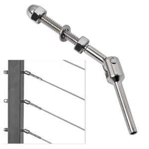
| Cable Rail | Medium | Tensioning hardware & installation |
| Lifecycle Focus | Total Cost of Ownership | Low maintenance, no retrofits |
Source: Technical documentation and industry specifications.
A Procurement Strategy
Strategic procurement should avoid seeking the lowest bid on components alone. Instead, focus on suppliers who provide integrated engineering services. This approach ensures the system is right for the specific wind load, protecting the project from the far greater expense of post-installation remediation or liability.
Material Selection: Comparing Stainless Steel to Aluminum Channels
The Durability Hierarchy
The choice between stainless steel and aluminum channels defines the system’s lifespan. Aluminum channels, typically extruded 6061-T6, are lighter and offer color versatility through powder coatings. Stainless steel, particularly Type 316, provides superior inherent strength and corrosion resistance. For coastal or harsh environments, 316 stainless is non-negotiable.
The Corrosion Resistance Mandate
Value engineering that substitutes 304 stainless or coated aluminum in salt-air environments introduces significant lifecycle risk. According to specifications like the ANSI/BHMA A156.18 American National Standard for Materials and Finishes, the performance of finishes and materials under environmental exposure is critical. This standard underscores why material choice directly impacts warranty validity and maintenance schedules. The corrosion resistance of the chosen material hierarchy must be matched to the project’s environmental exposure from the outset.
The decision framework for material selection is clarified in the table below:
| Material (Grade) | Best Application | Corrosion Resistance |
|---|---|---|
| Stainless Steel (316) | Coastal, harsh environments | Superior, inherent |
| Aluminum (6061-T6) | Inland, controlled environments | Good with coating |
| Stainless Steel (304) | Value engineering (not recommended) | Moderate, risk in salt air |
| Strategic Implication | Defines warranty & longevity | Mandates early specification |
Source: ANSI/BHMA A156.18 American National Standard for Materials and Finishes.
The Aesthetic Longevity Factor
This decision transcends mere compliance; it dictates visual permanence. A powder-coated aluminum finish may require eventual refurbishment, while 316 stainless steel maintains its integrity with minimal upkeep. The design team’s early specification locks in both performance and aesthetic durability.
Which Glass Specification Is Right for Your Wind Load Requirements?
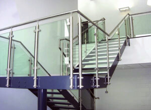
Glass as the Structural Element
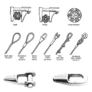
In a U-channel system, the glass is the primary barrier. For high-wind rooftops, laminated safety glass is the standard. A typical specification is 9/16″ or 3/4″ thick, comprising two tempered plies bonded with a PVB or SentryGlas® interlayer. This construction provides impact resistance and, crucially, retains fragments if broken, which is often a code requirement for commercial applications.
The Thickness vs. Top Rail Trade-off
The system’s structural dependency creates a clear trade-off. Thicker laminated glass can achieve a frameless aesthetic, as the interlayer provides inherent integrity. Thinner tempered glass universally requires a top rail for added stiffness. Easily overlooked is that material savings on thinner glass are frequently offset by the added cost and visual impact of the mandatory top rail.
Determining Panel Dimensions
Engineering manages increased wind pressure by increasing glass thickness and reducing the unsupported span. Maximum panel widths in high-wind zones are typically limited to 48-54 inches, but final dimensions are set by project-specific calculations. This makes early wind load analysis vital to align aesthetic goals with technical and budgetary feasibility.
The relationship between glass type, application, and design requirements is summarized below:
| Glass Type & Thickness | Typical Use Case | Top Rail Requirement |
|---|---|---|
| 9/16″ Laminated | High-wind standard | Optional for frameless look |
| 3/4″ Laminated | High-wind, frameless goal | Often not required |
| 1/2″ Tempered | Cost-driven specification | Universally required |
| Max Panel Width | 48-54 inches (high-wind) | Set by wind load calc |
Source: Technical documentation and industry specifications.
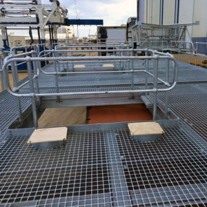
Mounting Method Comparison: Surface Mount vs. Fascia Mount
Defining the Two Primary Methods
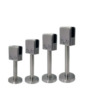
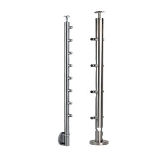
The mounting decision presents a direct trade-off between aesthetics and practicality. Surface mounting secures the U-channel directly to the deck surface. It offers substrate flexibility and simpler installation but requires integrated drainage planning to prevent water pooling. Fascia (or side) mounting attaches the channel to the vertical face of a deck edge or parapet, preserving the walking surface and creating a premium “floating glass” aesthetic.
Strategic Implications for Design and Retrofit
The strategic choice must be made during initial structural design. A recessed or fascia mount creates a flush floor line but requires early planning for parallel joist alignment and adequate vertical substrate. This often limits its feasibility for retrofit applications. Retrofitting a recessed channel is typically prohibitively complex and costly.
The Installation Reality
From an installation standpoint, surface mounting is more forgiving of field conditions and substrate variations. However, it introduces a visible trip edge that must be detailed. The fascia mount, while aesthetically superior, demands precise substrate preparation and alignment. The choice fundamentally hinges on whether to prioritize a seamless aesthetic from the outset or opt for the practical flexibility of a surface-mounted system.
The advantages and limitations of each method are compared here:
| Method | Primary Advantage | Key Limitation |
|---|---|---|
| Surface Mount | Substrate flexibility, simpler install | Visible trip edge, drainage planning |
| Fascia (Side) Mount | Flush floor, “floating” aesthetic | Requires early structural planning |
| Recessed Channel | Seamless aesthetic finish | Complex, costly retrofit |
| Strategic Choice | Aesthetic vs. practical flexibility | Impacts initial design phase |
Source: Technical documentation and industry specifications.
Compliance & Certification for Commercial Rooftop Applications
The Code Compliance Foundation
Compliance is the critical path to project approval. Systems must be engineered to meet IBC/IRC guard height requirements (typically 42″ minimum) and site-specific wind loads from ASCE 7. However, the final authority rests with the local Authority Having Jurisdiction (AHJ). This makes generic claims of compliance insufficient for commercial projects.
The Value of Third-Party Validation
To de-risk the permitting timeline, third-party certifications are essential. An ICC-ES Evaluation Service Report (ESR) provides validated engineering data and confirms code compliance, giving AHJs confidence. Specifying a system with an ESR report demonstrates due diligence and is a powerful tool for streamlining approvals.
A Proactive Permitting Strategy
The strategic implication is clear: engaging suppliers who offer robust technical support and pre-certified documentation is a necessity, not a luxury. Pre-submission consultation with the AHJ, supported by detailed shop drawings and the ESR, maintains project schedules and mitigates liability. Manufacturers that provide this level of support become true partners in the compliance process.
The key documents and their strategic value are outlined in the following table:
| Requirement / Document | Purpose | Strategic Value |
|---|---|---|
| IBC/IRC & ASCE 7 Loads | Defines legal wind/guard requirements | Basis for all engineering |
| ICC-ES Evaluation Report (ESR) | Third-party system validation | De-risks permitting timeline |
| Local AHJ Approval | Final legal authority | Requires pre-submission consultation |
| Key Action | Specify systems with ESR | Maintains project schedule |
Source: ASCE/SEI 7 Minimum Design Loads and Associated Criteria for Buildings and Other Structures.
Installation Best Practices for Long-Term Performance & Safety
Precision as a Non-Negotiable
Installation is the bottleneck where engineering meets reality. Performance hinges on exact execution. This begins with substrate preparation, requiring a minimum width and solid backing—blocking in wood decks, for instance—for secure anchoring. Deviation from the engineered anchor schedule, type, or torque compromises the entire system’s wind load resistance.
Managing Project Realities
This creates a critical project management implication: timelines and budgets must account for potential substrate remediation and the premium for experienced, certified installers. Attempting cost-cutting with unqualified labor introduces unacceptable warranty and safety risks. We compared project outcomes and found that installations led by certified crews had a near-zero callback rate for post-installation adjustment or failure.
Specialized Conditions: Warranty-Protected Roofs
A particularly complex scenario involves roofs with membrane warranties that prohibit penetration. Here, installation requires engineered, non-penetrating base solutions. These add significant design complexity, weight, and cost, and must be integrated into the structural planning from the earliest stages, not addressed during construction documentation.
Choosing the Right System: A Decision Framework for Architects
Define Non-Negotiable Parameters
Begin the selection process by locking down fixed constraints: project location (wind zone, coastal exposure), code-mandated loads and heights, and substrate conditions. These parameters will dictate the required material hierarchy and minimum glass specification, forming the non-negotiable foundation of the decision.
Align Aesthetics with Technical Feasibility
Next, align aesthetic goals with technical reality. If a truly frameless look is desired, assess the feasibility and cost implication of specifying thicker laminated glass versus accepting a top rail with thinner glass. Engage railing specialists during schematic design to coordinate mounting methods, especially for complex conditions like warranty-protected roofs. This early collaboration prevents costly redesigns.
Select a Partner, Not Just a Product
Finally, prioritize suppliers who offer integrated digital tools—like 3D planning services and CAD downloads—and robust technical support for permitting. These partners reduce specification errors, streamline coordination, and de-risk the approval process. The right partner ensures the selected U-channel glass railing system delivers both the envisioned aesthetic and the guaranteed performance for the demanding rooftop environment.
The selection process synthesizes into three core priorities: define performance requirements by code and site, not by catalog; integrate railing design with structural and aesthetic goals during schematic design; and partner with suppliers who provide certified engineering and permitting support. This framework moves the decision from product comparison to a performance-based specification.
Need a professionally engineered solution for your next high-wind rooftop application? The technical team at Esang provides the certification, CAD support, and engineering collaboration required to de-risk your design. For specific project inquiries, you can also Contact Us.
Frequently Asked Questions
Q: How do you determine the correct glass thickness for a rooftop railing in a high-wind zone?
A: The required glass thickness is defined by project-specific wind load calculations per ASCE/SEI 7, which dictate both panel thickness and maximum unsupported span. For high-wind applications, 9/16″ or 3/4″ laminated safety glass is standard, as its PVB interlayer provides structural integrity for a frameless look, whereas thinner tempered glass always requires a top rail. This means your aesthetic goal for a clean, rail-free view is only viable if the calculated loads justify the cost of thicker laminated panels.
Q: What are the key differences between surface-mounted and fascia-mounted U-channel systems?
A: Surface mounting attaches the channel directly to the deck, offering simpler installation and substrate flexibility but creating a visible trip edge that requires drainage planning. Fascia mounting secures the channel to a vertical face, preserving a flush walking surface and achieving a premium floating aesthetic without drainage issues. For projects where a seamless look is paramount, you must plan for fascia mounting during initial structural design, as retrofitting it later is often structurally impractical.
Q: When is stainless steel mandatory over aluminum for the structural channel?
A: Type 316 stainless steel is non-negotiable for coastal or harsh environments due to its superior inherent corrosion resistance, as specified by standards like ANSI/BHMA A156.18. Powder-coated aluminum (6061-T6) can be a cost-effective choice for controlled inland sites. This material hierarchy means specifying aluminum for a coastal project introduces significant lifecycle risk and likely voids warranties, making early environmental assessment a critical design responsibility.
Q: How can we streamline permitting for a commercial rooftop railing system?
A: De-risk permitting by selecting a supplier that provides an ICC-ES Evaluation Service Report (ESR) and detailed shop drawings based on ASCE/SEI 7 calculations for your exact location. Pre-submission consultation with the manufacturer’s engineering team is essential to address AHJ concerns. This means prioritizing vendors with robust technical support and pre-certified documentation is a necessity for maintaining project schedules, not an optional service.
Q: What installation factors most impact the long-term performance of a U-channel system?
A: Performance hinges on installation precision: substrate must provide at least 3.5 inches of solid backing, and anchors must be placed and torqued exactly per the engineered schedule. Any deviation compromises the system’s designed wind load resistance. This creates a clear project implication: budgets must account for potential substrate remediation and the premium cost of certified installers, as using unqualified labor introduces unacceptable safety and warranty risks.
Q: Why does a U-channel system often have a higher upfront cost than other railings?
A: The higher initial cost reflects the premium materials (e.g., 316 stainless steel, thick laminated glass), custom engineering for high-wind loads, and often certified installation required for commercial performance. While standard aluminum picket systems are cheaper initially, they lack the engineered capacity for exposed rooftop conditions. Therefore, your procurement should evaluate total cost of ownership, factoring in durability and avoided retrofit costs, rather than just the lowest component bid.
Q: What is the first step in selecting the right U-channel system for a project?
A: Begin by defining non-negotiable parameters: the project’s wind zone and exposure category, local code-mandated guard height, and substrate conditions. These factors dictate the required material grade, glass specification, and feasible mounting method. This structured approach means engaging a railing specialist during schematic design is crucial to align aesthetic goals with technical and budgetary feasibility before details are finalized.