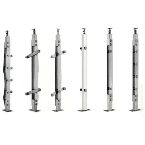
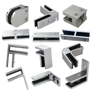
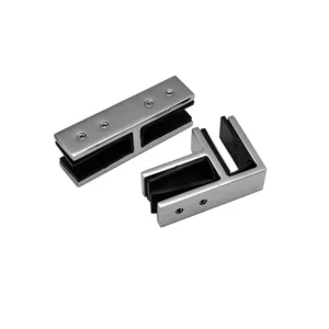
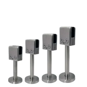
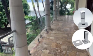
Core-drill glass spigots place an extended stem into a prepared pocket in concrete, giving a smaller visible footprint than a surface base plate. They are useful only when the structure, edge distance, coring access, embedment material and drainage can be confirmed before site work. Send the slab detail, glass layout and approximate quantity to begin; do not core holes from a generic spigot name.
Discuss core-drill spigots on WhatsApp
Use an embedded stem only where the structure allows it
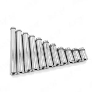
A core-drill spigot differs from a surface-mount spigot at the connection to the structure. Its lower stem enters a drilled or formed pocket and is restrained by the specified setting material or engineered connection. That can reduce visible hardware, but it makes the hole geometry and installation sequence critical.
- Suitable concrete: confirm the structural concrete depth, strength information, edge distance, reinforcement, post-tensioning, embedded services and access for drilling. Pavers, tile, screed and topping layers do not establish the supporting depth.
- Controlled pocket: hole diameter, depth, plumb, cleanliness and dryness or moisture condition must match the exact spigot and setting-material instructions. An oversized, shallow, contaminated or misaligned pocket changes restraint and panel alignment.
- Water management: identify exterior exposure, drainage path, seal or dress-ring detail and waterproofing responsibility. Trapped water, slurry or an interrupted membrane can create maintenance and building-envelope problems even when the visible spigot looks correct.
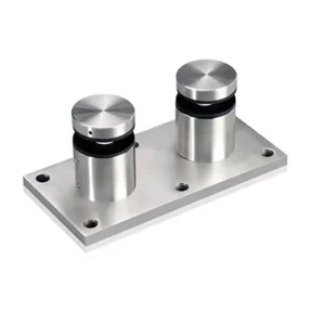
Where coring is restricted or a removable top-fix connection is preferred, compare a surface-mount spigot and its base-plate anchor group instead.

Freeze the pocket and finished level together
Core-drill work is difficult to move after the slab is cut. Coordinate the centreline, pocket depth and finished floor level before drilling. The quotation and installation drawing should identify:
- spigot stem form, overall length and the datum used to set its exposed height;
- required pocket diameter and depth for that exact configuration;
- proposed non-shrink grout, resin or other setting method and whose instructions govern preparation and cure;
- temporary bracing and alignment method while the setting material develops strength;
- dress ring, seal and drainage arrangement at the finished surface;
- minimum structural edge conditions and any no-drill zones supplied by the project engineer.
A pocket that is correct relative to the rough slab may leave the spigot too low after pavers or too high after a finish change. Conversely, packing the visible part to correct a bad datum can reduce the intended embedment or leave unsupported gaps.
Match glass, liners and clamping method
The upper pocket must be matched to the actual glass, not only its nominal thickness. Confirm monolithic or laminated construction, total thickness and tolerance, heat-treatment requirement, panel height and width, interlayer where relevant, and the project’s edge and gap details.
Ask the proposed configuration to state the liners, packers, setting block, pressure piece and clamping screws supplied. Their thickness and placement control metal-to-glass separation and panel alignment. Many friction-type spigots accept an un-drilled lower glass edge, but that must be confirmed from the exact drawing before glass fabrication; do not assume every core-drill spigot uses the same retention method.
Plan adjustment before the grout cures
There are two different kinds of correction, and they should not be confused:
- Spigot alignment in the pocket sets centreline, plumb and exposed height during installation. Once the setting material cures, large corrections may require removal and rework.
- Glass adjustment in the pocket uses the stated liners, packers or clamp adjustment to fine-tune panel position. It cannot compensate for a badly located core hole or an unsuitable substrate.
The installer should receive the approved setting-out drawing, tolerance sequence and tightening instructions before the first hole is cut. Trialing the exact spigot, packer set and glass sample can reveal a mismatch before a full run is drilled.
Define the complete supply boundary
Request a quote that distinguishes the spigot hardware from the complete railing and the site works. It should state whether the following are included:
- spigot body, glass-contact set, clamp fasteners and dress ring;
- grout, resin, sealant, drainage accessory or installation template;
- glass panels and any required fabrication;
- top rail, panel connectors, gate hardware and end restraints;
- installation drawings, test reports, material records and project engineering;
- coring, scanning, waterproofing repair, setting, cleaning and site protection.
A component material statement or spigot photograph is not a compliance result for the installed guard. Performance depends on the tested or engineered combination of glass, spigot spacing, clamp components, embedment, concrete and any rail or connectors required by the project.
What to send for a comparable quotation
An early request can use estimated quantities, but the final proposal should resolve the fields that control drilling and glass fabrication. Send:
- project location, exposure and intended guard, screen or barrier use;
- plan/elevation, panel sizes, corners, slopes, gates and desired centreline;
- glass make-up and thickness, or the design stage if still open;
- structural concrete depth, edge distances, finishes and waterproofing layers;
- known reinforcement, post-tensioning or services restrictions;
- preferred visible form, finish, quantity and packaging needs;
- whether glass, setting material, dress rings, tools, drawings or evidence are required in the proposed supply.
Ask the quote to repeat the exact stem, pocket, glass-contact and setting assumptions. Those are the comparison fields that prevent a low-profile detail from becoming a drilling or alignment problem on site.